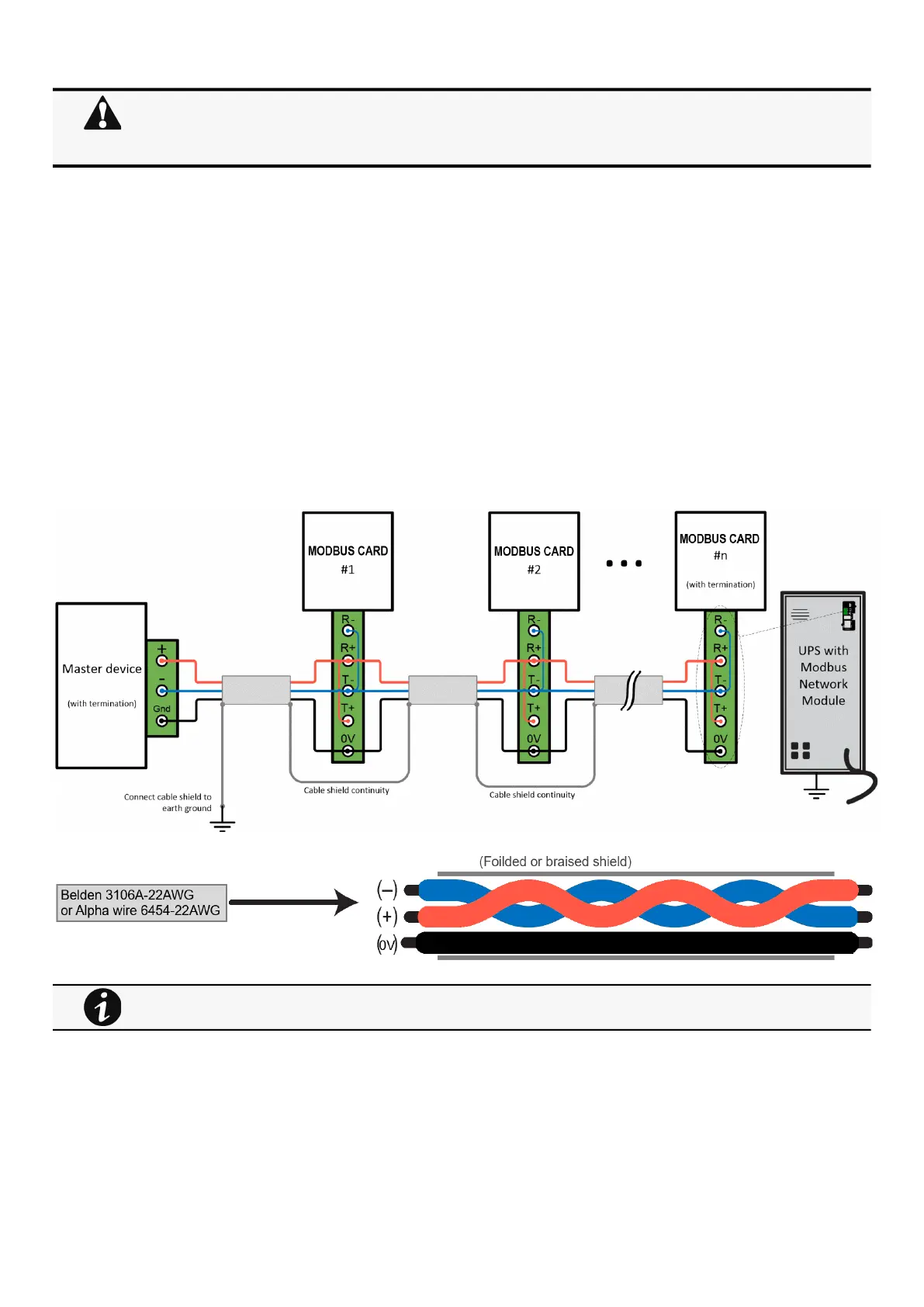
Wiring the RS-485 Modbus RTU terminal
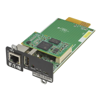
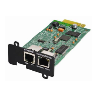
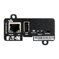
Installing the Network Management Module – 11
•
•
•
2.3.1 Modbus Common/GND (0V pin on terminal block)connection
The Network Module is an isolated device, if all the other devices on the network are isolated, common/GND (0V pin on terminal
block) should be connected between devices to limit common mode voltage.
Common/GND (0V pin on terminal block) should not be connected to any other devices that is not isolatedto avoid ground loops.
2.3.2 Cable shield connection (foiled or braised)
The cable shield should be continuous on the entire length of the bus and should be connected to ground (earth) at only one point
to limit the flow of ground-loop currents in the shield caused by ground potential differences.
2.3.3 Two-wire networks
Interconnect R- with T- and R+ with T+ onthe Modbus Network Moduleterminal strip.
Connect the RS-485 network signal + to the R+ or T+ on the Modbus Network Moduleterminal strip.
Connect the RS-485 network signal – to the R- or T- on the ModbusNetwork Moduleterminal strip.
2.3.4 Four-wire networks
All four RS-485 network signals including T-, T+, R–, and R+ must be connected respectively to the terminal strip R-, R+, T-, T+.
If the Modbus Network Module is the last device installed in the network chain or the length of the network cable is
excessive, termination needs to be enabled.
For details on termination, see theInstalling the Network Management Module>>>Wiring the RS-485 Modbus
RTU terminal>>>Configuring the termination
section.
Belden 3106A-22AWG or equivalent cabling (a 1.5 twisted-pair shielded 120Ω cable with ground) is recommended.