Servicing the EMP – 203
6.3 Installing the EMP
6.3.1 Defining EMPs address and termination
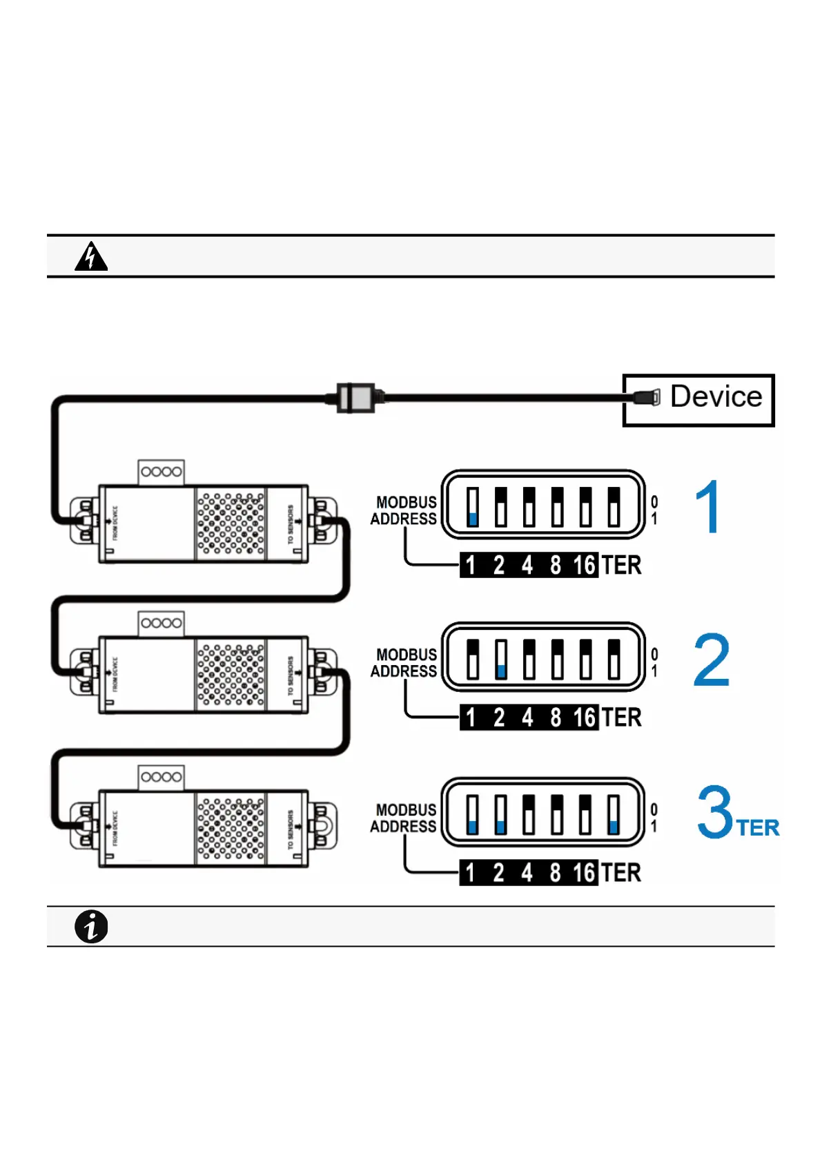
6.3.1.1 Manual addressing
Define different address for all the EMPs in the daisy-chain.
Set the RS485 termination (TER) to 1 on the last EMP of the daisy chain, set it to 0 on all the other EMPs.
6.3.1.1.1 Example:manual addressing of 3 EMPs connected to the Device
6.3.2 Mounting the EMP
The EMP includes magnets, cable ties slots and keyholes to enable multiple ways of mounting it on your installation.
Address must be defined before the EMP power-up otherwise the changes won't be taken into account.
Do not set Modbus address to 0,otherwise the EMP will not be detected.
Green LED of the TO DEVICE RJ45 connector shows if the EMP is powered by the Network module.