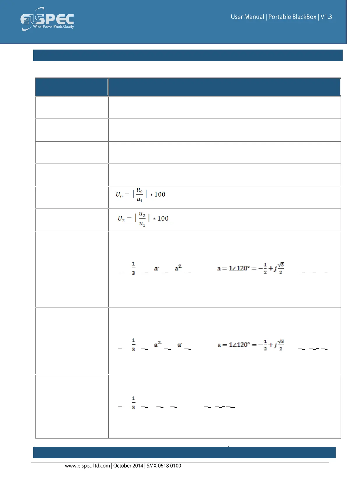
table - unbalance section (Avg, Min, Max) parameters calculation method:
The table outlines the sections' Parameters including Calculation:
The Supply Voltage Unbalance is Evaluated Using the Method of
Symmetrical Components in Accordance with IEC61000-4-30
The Average Supply Voltage Unbalance is Evaluated Using the Method of
Symmetrical Components in Accordance with IEC61000-4-30
The Minimum Supply Voltage Unbalance is Evaluated Using the Method of
Symmetrical Components in Accordance with IEC61000-4-30
The Maximum Supply Voltage Unbalance is Evaluated Using the Method of
Symmetrical Components in Accordance with IEC61000-4-30
Negative Sequence
Unbalance
Defined as the symmetrical vector system derived by application of the
Fortescue’s transformation matrix, and that rotates in the same direction
as the power frequency voltage (or current):
U
1
= (U
a
+
U
b
+ U
c
) where and U
a
, U
b
,
U
c
and are line to neutral voltages (fundamental component)
In Accordance With IEC61000-3-13, ed. 1.0 (2008-02) Ref: 3.26.3
Defined as the symmetrical vector system derived by application of the
Fortescue’s transformation matrix, and that rotates in the opposite
direction to the power frequency voltage (or current):
U
1
= (U
a
+ U
b
+ U
c
) where and U
a
, U
b
,
U
c
and are line to neutral voltages (fundamental component)
In Accordance With IEC61000-3-13, ed. 1.0 (2008-02) Ref: 3.26.4
Defined as the in-phase symmetrical vector system derived by application
of the Fortescue’s transformation matrix:
U
0
= (U
a
+ U
b
+ U
c
) where U
a
, U
b
,
U
c
and are line to neutral voltages
(fundamental component)
In Accordance With IEC61000-3-13, ed. 1.0 (2008-02) Ref: 3.26.5
DC VOLTAGE & CURRENT SECTION (rms, Min, Max):