22 100-412-183 REV. 13
2.4.2 DCX S Power Supply Connections
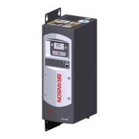
Figure 2.5 DCX S Power Supply Back Panel (Horizontal)
Figure 2.6 DCX S Power Supply Bottom Panel (Vertical)
Table 2.5 Connections to the DCX S Power Supply
Item Name Function
1
Circuit Breaker /
Power Switch
Turns the AC main power on or off.
2
Line Input
Connector
Detachable connector block for connecting the input power.
For wiring details refer to Chapter 5: Installation and
Setup.
3
User I/O
Connector
Provides the necessary input/output signals to interface
with user automation or control interfaces. For detailed
information on interfacing with the DCX S Power Supply
refer to Chapter 5: Installation and Setup.
4 RF Connector
SHV connector for RF cable, which provides ultrasonic
energy to the converter.
5 Ground Screw Ground screw to serve as a redundant safety measure.
4
2
3
1
5
1
2
4
3
5