DL8000 Preset Instruction Manual
1-4 Overview Revised February-2016
Note: For specific details, refer to the technical specification DL8000
Preset (part D301255X012), available at
www.EmersonProcess.com/Remote.
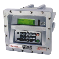
Front cover bolts
B
Display
Status LEDs
D
Weights & Measures switch
Operator keypad
Figure 1-2. DL8000 (in Class I, Zone 1 Enclosure)
Sixteen stainless steel front cover bolts (M10 – 1.5 metric) secure the lid
to the housing. Two of the front bolts are longer and drilled close to the
threaded ends, allowing placement of Weight & Measures seal wires to
prevent undetected access to the electronics.
Bolt holes are tapped to 13 mm (0.50 inches); require an 8 mm (5/16-
inch) Allen wrench, and torque to 24 to 29 Newton/meters (18 to 21
foot/pounds) of force.
The operator keypad provides 18 rugged, Hall-Effect pushkeys which
are impervious to chemicals commonly associated with petroleum
applications. A sealable Weights & Measures switch provides security
to flow measurement parameters.
Secured behind non-glare glass, the liquid crystal display (LCD)
provides an 8-line by 40-column message area for operator interface.
The display uses a photo sensor and temperature sensor which can be
set to automatically adjust contrast and backlighting for optimal
viewing.
Light-emitting diodes (LEDs) displaying the status of alarms, operating
mode, and permissive powers are located to the right of the display.

 Loading...


