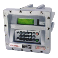
DL8000 Preset Instruction Manual
Revised February-2016 Modbus Communications B-21
3. Review the values in the following fields:
Logical Point
Indicates the logical point for the communications
port. Click to display all available logical points.
Tag
Indicates a label associated with the logical point.
Enter up to 10 alphanumeric characters.
RTU Address
Indicates the RTU address of the slave device to be
queried.
Function Code
Indicates the Modbus function code to be sent to the
slave device.
Slave Register
Indicates the starting Modbus register number for the
query on this slave device.
Master Register
Indicates the starting Modbus register number where
the queried data is stored on the master DL8000
device.
Number of
Registers
Indicates the total number of registers in the range.
Comm Status
This read-only field shows the status of the query.
Valid values include:
0
Inactive or start of transmission.
1
Receive timeout error.
2
Received address check.
3
Received function number check.
4
Number of expected bytes check.
5
Receiving slave response.
6
CRC or LRC check.
7
CRC or LRC check.
8
Valid slave response.
128
Write device data error.
129
Access device data error.
130
Host function table error.
131
Transmit timeout error.
144
Transmit or receive buffer overflow.
145
Invalid function number in request.
4. Click Apply to save any changes you have made to this screen.
5. Proceed to Section B.7 to configure Modbus master modem values.

 Loading...


