Emerson Process Management GmbH & Co. OHG2-18
X-STREAM X2FD
Instruction Manual
HASXMDE-IM-EX
01/2015
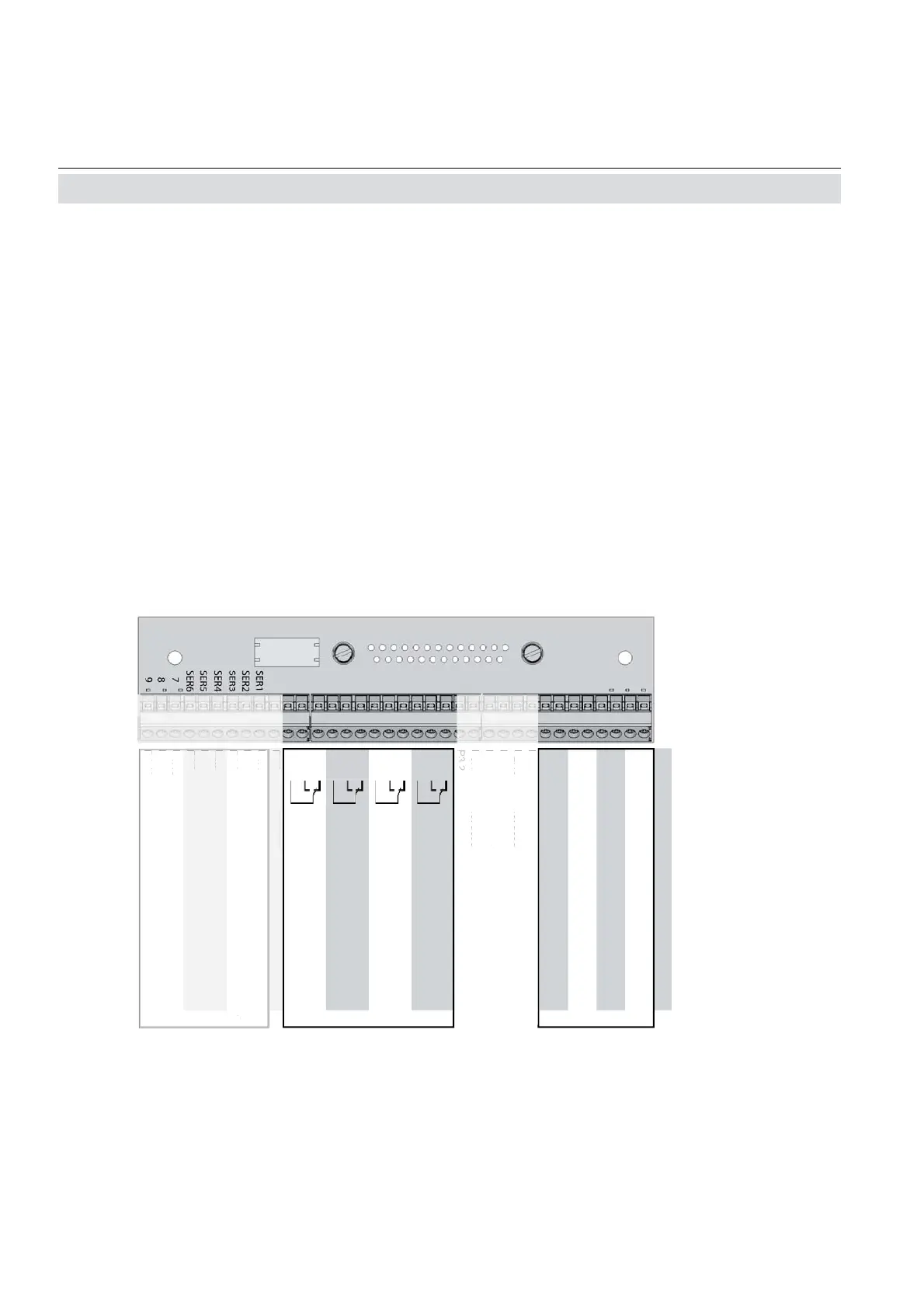
Pin Signal
P2.1 Channel 1, (+) 4 (0) - 20 mA
P2.2 Channel 1, GND
P2.3 Channel 2, (+) 4 (0) - 20 mA
P2.4 Channel 2, GND
P2.5 Channel 3, (+) 4 (0) - 20 mA
P2.6 Channel 3, GND
P2.7 Channel 4, (+) 4 (0) - 20 mA
P2.8 Channel 4, GND
P2.9 not used
P2.10 not used
P2.11 not used
P2.12 not used
P3.1 not used
P3.2 not used
P3.3 Output 1 ( Failure), NC
P3.4 Output 1 ( Failure), NO
P3.5 Output 1 ( Failure), COM
P3.6 Output 2 ( Maintenance Request), NC
P3.7 Output 2 ( Maintenance Request), NO
P3.8 Output 2 ( Maintenance Request), COM
P3.9 Output 3 (Out of Spec), NC
P3.10 Output 3 (Out of Spec), NO
P3.11 Output 3 (Out of Spec), COM
P3.12 Output 4 ( Function check), NC
P4.1 Output 4 ( Function check), NO
P4.2 Output 4 ( Function check), COM
P4.3 not used
P4.4
P4.5
P4.6
P4.7
P4.8
P4.9
P4.10
P4.11
P4.12
Relay Outputs
**)
Analog Outputs
Serial Interface
*)
**)
Confi guration of relay output termi-
nals as per standard factory setting
(NAMUR status signals)
Fig. 2-11: Terminals block X1 - analog signals and relay outputs 1-4
Analog Outputs
Relay Outputs 1 - 4
Terminals for analog signals and relais outputs
1 - 4 are located at the leftmost terminal module
(terminal block X1; fi g. 2-5).
Analog outputs specifi cation: 4 (0) - 20 mA; burden: R
B
≤ 500 Ω
Specifi cation of relay outputs 1-4: Dry
relay change-over contacts
can be used as NO or NC.
Electrical specifi cation: max. 30 VDC, 1 A, 30 W
2.5 Installation - Electrical
Note!
Take care of the special installation instruc-
tions in section 4.5 of the X-STREAM gas
analyzer series manual!
**)
Confi guration of relay output termi-
nals as per standard factory setting
(NAMUR status signals)
P4.
n
t
P4.4
P4.
P4.
P4.
P4.
P4.
P4.1
P4.1
P4.1
erial Inter
ac
P2.
n
t
P2.1
n
t
P2.1
n
t
n
t
P
.
n
t
 Loading...


