Safety
Information
Introduction
Product
Information
System
configuration
Mechanical
Installation
Electrical
Installation
Getting
Started
Basic
parameters
Running
the motor
Optimization
SMARTCARD
operation
Onboard
PLC
Advanced
parameters
Technical
Data
Diagnostics
UL Listing
Information
Unidrive SPM User Guide 119
Issue Number: 3 www.controltechniques.com
When a keypad is installed, this parameter enables the forward/reverse
key.
This parameter shows the number of the data block last transferred from
a SMARTCARD to the drive.
* Modes 1 and 2 are not user saved, Modes 0, 3 and 4 are user saved.
N
If Pr 0.30 is equal to 1 or 2 this value is not transferred to the EEPROM
or the drive. If Pr 0.30 is set to a 3 or 4 the value is transferred.
For further information, please refer to Chapter 11 SMARTCARD
operation on page 149.
Pr 0.31 indicates the voltage rating of the drive.
Pr 0.32 indicates the maximum continuous Heavy Duty current rating.
Open-loop
When the drive is enabled with Pr 0.33 = 0, the output frequency starts at
zero and ramps to the required reference. When the drive is enabled
when Pr 0.33 has a non-zero value, the drive performs a start-up test to
determine the motor speed and then sets the initial output frequency to
the synchronous frequency of the motor. Restrictions may be placed on
the frequencies detected by the drive as follows:
Closed-loop vector
The motor rated full load rpm parameter (Pr 0.45) in conjunction with the
motor rated frequency parameter (Pr 0.46) defines the full load slip of the
motor. The slip is used in the motor model for closed-loop vector control.
The full load slip of the motor varies with rotor resistance which can vary
significantly with motor temperature. When Pr 0.33 is set to 1 or 2, the
drive can automatically sense if the value of slip defined by Pr 0.45 and
Pr 0.46 has been set incorrectly or has varied with motor temperature. If
the value is incorrect parameter Pr 0.45 is automatically adjusted. The
adjusted value in Pr 0.45 is not saved at power-down. If the new value is
required at the next power-up it must be saved by the user.
Automatic optimisation is only enabled when the speed is above 12.5%
of rated speed, and when the load on the motor load rises above 62.5%
rated load. Optimisation is disabled again if the load falls below 50% of
rated load.
For best optimisation results the correct values of stator resistance (Pr
5.17), transient inductance (Pr 5.24), stator inductance (Pr 5.25) and
saturation breakpoints (Pr 5.29, Pr 5.30) should be stored in the relevant
parameters. These values can be obtained by the drive during an
autotune (see Pr 0.40 for further details).
Rated rpm auto-tune is not available if the drive is not using external
position/speed feedback.
The gain of the optimiser, and hence the speed with which it converges,
can be set at a normal low level when Pr 0.33 is set to 1. If this
parameter is set to 2 the gain is increased by a factor of 16 to give faster
convergence.
If any number other than 0 is programmed into this parameter, user
security is applied so that no parameters except parameter 0.49 can be
adjusted with the keypad. When this parameter is read via a keypad it
appears as zero.
For further details refer to section 7.9.3 User Security on page 106.
This parameter defines the communications protocol used by the
EIA485 comms port on the drive. This parameter can be changed via the
drive keypad, via a Solutions Module or via the comms interface itself. If
it is changed via the comms interface, the response to the command
uses the original protocol. The master should wait at least 20ms before
send a new message using the new protocol. (Note: ANSI uses 7 data
bits, 1 stop bit and even parity; Modbus RTU uses 8 data bits, 2 stops
bits and no parity.)
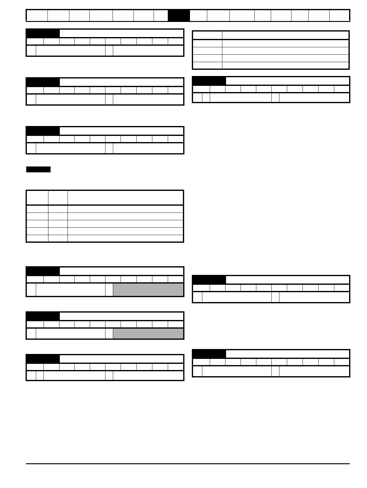
0.28 {6.13} Keypad fwd/rev key enable
RW Bit US
Ú
OFF (0) or On (1)
Ö
OFF (0)
0.29 {11.36} SMARTCARD parameter data
RO Uni NC PT US
Ú
0 to 999
Ö
0
0.30 {11.42} Parameter copying
RW Txt NC *
Ú
0 to 4
Ö
nonE (0)
Pr
String
Pr
value
Comment
nonE 0 Inactive
rEAd 1 Read parameter set from the SMARTCARD
Prog 2 Programming a parameter set to the SMARTCARD
Auto 3 Auto save
boot 4 Boot mode
0.31 {11.33} Drive rated voltage
RO Txt NC PT
Ú
200V (0), 400V (1), 575V (2),
690V (3)
Ö
0.32 {11.32} Maximum Heavy Duty current rating
RO Uni NC PT
Ú
0.00 to 9,999.99 A
Ö
0.33 {6.09} Catch a spinning motor
RW Uni US
OL
Ú
0 to 3
Ö
0
Pr 0.33 Function
0 Disabled
1 Detect all frequencies
2 Detect positive frequencies only
3 Detect negative frequencies only
0.33 {5.16} Rated rpm autotune
RW Uni US
VT
Ú
0 to 2
Ö
0
0.34 {11.30} User security code
RW Uni NC PT PS
Ú
0 to 999
Ö
0
0.35 {11.24} Serial comms mode
RW Txt US
Ú
AnSI (0), rtu (1), Lcd (2)
Ö
rtU (1)

 Loading...


