Safety
Information
Introduction
Product
Information
System
configuration
Mechanical
Installation
Electrical
Installation
Getting
Started
Basic
parameters
Running
the motor
Optimization
SMARTCARD
operation
Onboard
PLC
Advanced
parameters
Technical
Data
Diagnostics
UL Listing
Information
120 Unidrive SPM User Guide
www.controltechniques.com Issue Number: 3
ANSIx3.28 protocol
Full details of the CT ANSI communications protocol are the Advanced
User Guide.
Modbus RTU protocol
Full details of the CT implementation of Modbus RTU are given in the
Advanced User Guide.
Modbus RTU protocol, but with an SM-Keypad only
This setting is used for disabling communications access when the SM-
Keypad is used as a hardware key.
* only applicable to Modbus RTU mode
This parameter can be changed via the drive keypad, via a Solutions
Module or via the comms interface itself. If it is changed via the comms
interface, the response to the command uses the original baud rate. The
master should wait at least 20ms before send a new message using the
new baud rate.
Used to define the unique address for the drive for the serial interface.
The drive is always a slave.
Modbus RTU
When the Modbus RTU protocol is used addresses between 0 and 247
are permitted. Address 0 is used to globally address all slaves, and so
this address should not be set in this parameter
ANSI
When the ANSI protocol is used the first digit is the group and the
second digit is the address within a group. The maximum permitted
group number is 9 and the maximum permitted address within a group is
9. Therefore, Pr 0.37 is limited to 99 in this mode. The value 00 is used
to globally address all slaves on the system, and x0 is used to address
all slaves of group x, therefore these addresses should not be set in this
parameter.
These parameters control the proportional and integral gains of the
current controller used in the open loop drive. The current controller
either provides current limits or closed loop torque control by modifying
the drive output frequency. The control loop is also used in its torque
mode during line power supply loss, or when the controlled mode
standard ramp is active and the drive is decelerating, to regulate the flow
of current into the drive.
Open-Loop
There are two autotune tests available in open loop mode, a stationary
and a rotating test. A rotating autotune should be used whenever
possible, so the measured value of power factor of the motor is used by
the drive.
• The stationary autotune can be used when the motor is loaded and it
is not possible to remove the load from the motor shaft.
• A rotating autotune first performs a stationary autotune, before
rotating the motor at
2
/
3
base speed in the forward direction for
several seconds. The motor must be free from load for the rotating
autotune.
To perform an autotune, set Pr 0.40 to 1 for a stationary test or 2 for a
rotating test, and provide the drive with both an enable signal (on
terminal 31) and a run signal (on terminal 26 or 27).
Following the completion of an autotune test the drive will go into the
inhibit state. The drive must be placed into a controlled disable condition
before the drive can be made to run at the required reference. The drive
can be put in to a controlled disable condition by removing the SAFE
TORQUE OFF (SECURE DISABLE) signal from terminal 31, setting the
drive enable parameter Pr 6.15 to OFF (0) or disabling the drive via the
control word (Pr 6.42 & Pr 6.43).
For further information refer to section Pr 0.40 {5.12} Autotune on
page 136.
Closed-loop
There are three autotune tests available in closed loop vector mode, a
stationary test, a rotating test and an inertia measurement test. A
stationary autotune will give moderate performance whereas a rotating
autotune will give improved performance as it measures the actual
values of the motor parameters required by the drive. An inertia
measurement test should be performed separately to a stationary or
rotating autotune.
• The stationary autotune can be used when the motor is loaded and it
is not possible to remove the load from the motor shaft.
• A rotating autotune first performs a stationary autotune, before
rotating the motor at
2
/
3
base speed in the forward direction for
approximately 30 seconds. The motor must be free from load for the
rotating autotune.
• The inertia measurement test can measure the total inertia of the
load and the motor. This is used to set the speed loop gains (see
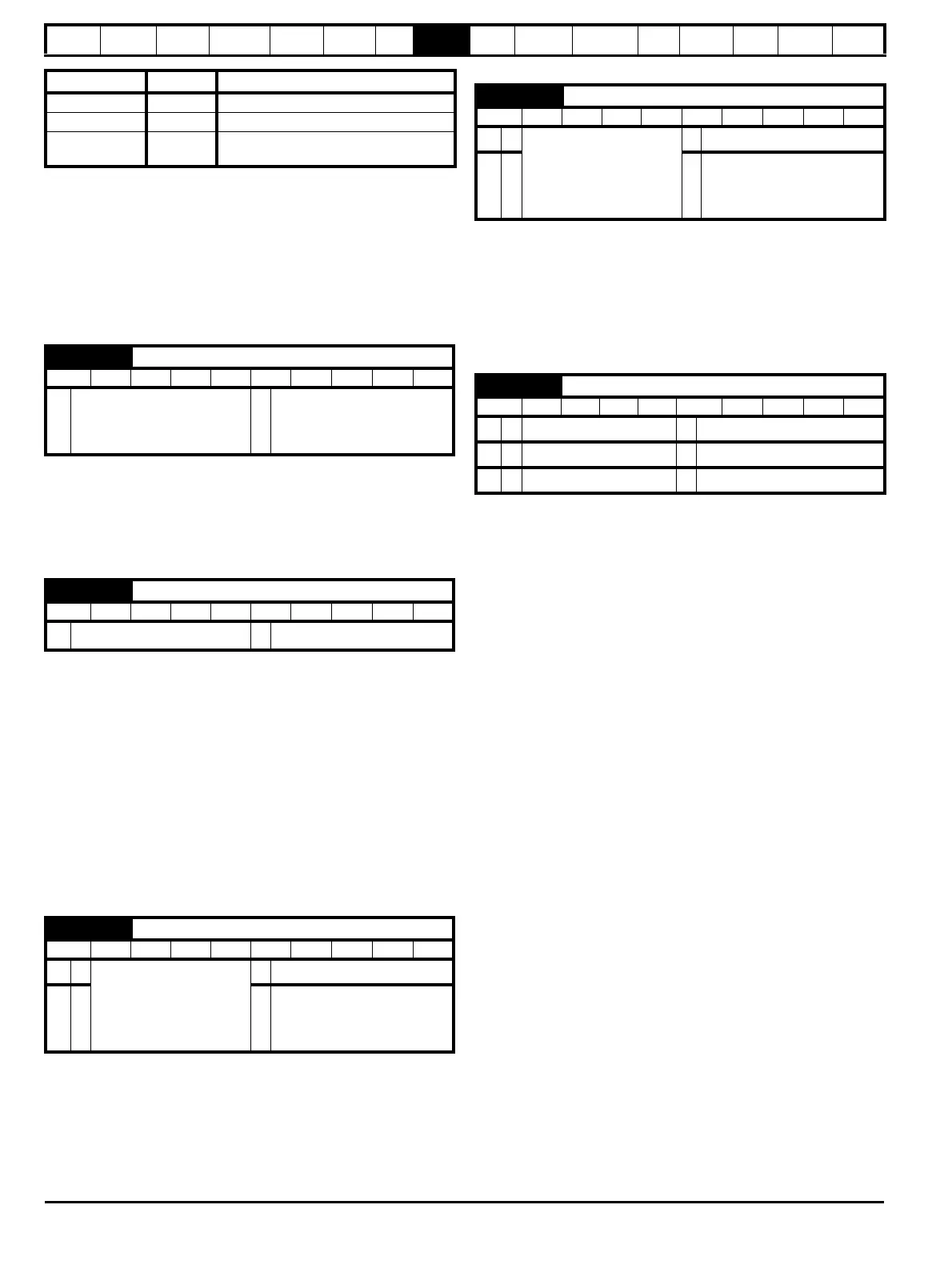
Comms value String Communications mode
0 AnSI ANSI
1 rtU Modbus RTU protocol
2Lcd
Modbus RTU protocol, but with an SM-
Keypad only
0.36 {11.25} Serial comms baud rate
RW Txt US
Ú
300 (0), 600 (1), 1200 (2),
2400 (3), 4800 (4), 9600 (5),
19200 (6), 38400 (7),
57600 (8)*, 115200 (9)*
Ö
19200 (6)
0.37 {11.23} Serial comms address
RW Uni US
Ú
0 to 247
Ö
1
0.38 {4.13} Current loop P gain
RW Uni US
OL
Ú
0 to 30,000
Ö
All voltage ratings: 20
CL
ÚÖ
200V drive: 75
400V drive: 150
575V drive: 180
690V drive: 215
0.39 {4.14} Current loop I gain
RW Uni US
OL
Ú
0 to 30,000
Ö
All voltage ratings: 40
CL
ÚÖ
200V drive: 1,000
400V drive: 2,000
575V drive: 2,400
690V drive: 3,000
0.40 {5.12} Autotune
RW Uni
OL
Ú
0 to 2
Ö
0
VT
Ú
0 to 4
Ö
0
SV
Ú
0 to 6
Ö
0

 Loading...


