Safety
Information
Introduction
Product
Information
System
configuration
Mechanical
Installation
Electrical
Installation
Getting
Started
Basic
parameters
Running
the motor
Optimization
SMARTCARD
operation
Onboard
PLC
Advanced
parameters
Technical
Data
Diagnostics
UL Listing
Information
Unidrive SPM User Guide 121
Issue Number: 3 www.controltechniques.com
Speed loop gains, below) and to provide torque feed forwards when
required during acceleration. During the inertia measurement test
the motor speed changes from
1
/
3
to
2
/
3
rated speed in the forward
direction several times. The motor can be loaded with a constant
torque load and still give an accurate result, however, non-linear
loads and loads that change with speed will cause measurement
errors.
To perform an autotune, set Pr 0.40 to 1 for a stationary test, 2 for a
rotating test, or 3 for an inertia measurement test and provide the drive
with both an enable signal (on terminal 31) and a run signal (on terminal
26 or 27).
Following the completion of an autotune test the drive will go into the
inhibit state. The drive must be placed into a controlled disable condition
before the drive can be made to run at the required reference. The drive
can be put in to a controlled disable condition by removing the SAFE
TORQUE OFF (SECURE DISABLE) signal from terminal 31, setting the
drive enable parameter Pr 6.15 to OFF (0) or disabling the drive via the
control word (Pr 6.42 & Pr 6.43).
Setting Pr 0.40 to 4 will cause the drive to calculate the current loop
gains based on the previously measured values of motor resistance and
inductance. The drive does apply any voltage to the motor during this
test. The drive will change Pr 0.40 back to 0 as soon as the calculations
are complete (approximately 500ms).
For further information refer to section Pr 0.40 {5.12} Autotune on
page 139.
Servo
There are five autotune tests available in servo mode, a short low speed
test, a normal low speed test, an inertia measurement test, a stationary
test and a minimal movement test. A normal low speed should be done
where possible as the drive measures the stator resistance and
inductance of the motor, and from these calculates the current loop
gains. An inertia measurement test should be performed separately to a
short low speed or normal low speed autotune.
• A short low speed test will rotate the motor by 2 electrical revolutions
(i.e. up to 2 mechanical revolutions) in the forward direction, and
measure the encoder phase angle. The motor must be free from
load for this test.
• A normal low speed test will rotate the motor by 2 electrical
revolutions (i.e. up to 2 mechanical revolutions) in the forward
direction. This test measures the encoder phase angle and updates
other parameters including the current loop gains. The motor must
be free from load for this test.
• The inertia measurement test can measure the total inertia of the
load and the motor. This is used to set the speed loop gains and to
provide torque feed forwards when required during acceleration.
During the inertia measurement test the motor speed changes from
1
/
3
to
2
/
3
rated speed in the forward direction several times. The
motor can be loaded with a constant torque load and still give an
accurate result, however, non-linear loads and loads that change
with speed will cause measurement errors.
• The stationary test only measures the motor resistance and
inductance, and updates the current loop gain parameters. This test
does not measure the encoder phase angle so this test needs to be
done in conjunction with either the short low speed or minimal
movement tests.
• The minimal movement test will move the motor through a small
angle to measure the encoder phase angle. This test will operate
correctly when the load is an inertia, and although a small amount of
cogging and stiction is acceptable, this test cannot be used for a
loaded motor.
To perform an autotune, set Pr 0.40 to 1 for a short low speed test, 2 for
a normal low speed test, 3 for an inertia measurement test, 4 for a
stationary test or 5 for a minimal movement test, and provide the drive
with both an enable signal (on terminal 31) and a run signal (on terminal
26 or 27).
Following the completion of an autotune test the drive will go into the
inhibit state. The drive must be placed into a controlled disable condition
before the drive can be made to run at the required reference. The drive
can be put in to a controlled disable condition by removing the SAFE
TORQUE OFF (SECURE DISABLE) signal from terminal 31, setting the
drive enable parameter Pr 6.15 to OFF (0) or disabling the drive via the
control word (Pr 6.42 & Pr 6.43).
Setting Pr 0.40 to 6 will cause the drive to calculate the current loop
gains based on the previously measured values of motor resistance and
inductance. The drive does apply any voltage to the motor during this
test. The drive will change Pr 0.40 back to 0 as soon as the calculations
are complete (approximately 500ms).
For further information refer to section Pr 0.40 {5.12} Autotune on
page 139.
This parameter defines the required switching frequency. The drive may
automatically reduce the actual switching frequency (without changing
this parameter) if the power stage becomes too hot. A thermal model of
the IGBT junction temperature is used based on the heatsink
temperature and an instantaneous temperature drop using the drive
output current and switching frequency. The estimated IGBT junction
temperature is displayed in Pr 7.34. If the temperature exceeds 145°C
the switching frequency is reduced if this is possible (i.e >3kHz).
Reducing the switching frequency reduces the drive losses and the
junction temperature displayed in Pr 7.34 also reduces. If the load
condition persists the junction temperature may continue to rise again
above 145°C and the drive cannot reduce the switching frequency
further the drive will initiate an ‘O.ht1’ trip. Every second the drive will
attempt to restore the switching frequency to the level set in Pr 0.41.
The full range of switching frequencies is not available on all ratings of
Unidrive SP. See section 10.5 Switching frequency on page 147, for the
maximum available switching frequency for each drive rating.
8.2.7 Motor parameters
Open-loop
This parameter is used in the calculation of motor speed, and in applying
the correct slip compensation. When auto is selected, the number of
motor poles is automatically calculated from the rated frequency (Pr
0.47) and the rated full load rpm (Pr 0.45). The number of poles = 120 *
rated frequency / rpm rounded to the nearest even number.
Closed-loop vector
This parameter must be set correctly for the vector control algorithms to
operate correctly. When auto is selected, the number of motor poles is
automatically calculated from the rated frequency (Pr 0.47) and the rated
full load rpm (Pr 0.45). The number of poles = 120 * rated frequency /
rpm rounded to the nearest even number.
Servo
This parameter must be set correctly for the vector control algorithms to
operate correctly. When auto is selected the number of poles is set to 6.
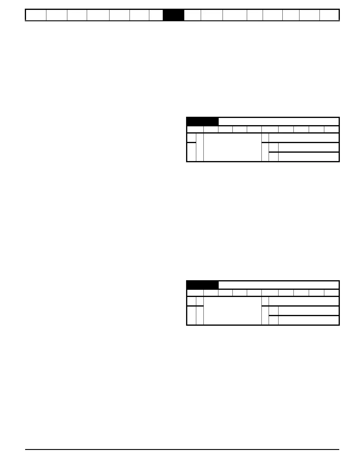
0.41 {5.18} Maximum switching frequency
RW Txt RA US
OL
Ú
3 (0), 4 (1), 6 (2)
Ö
3 (0)
CL
Ö
VT 3 (0)
SV 6 (2)
0.42 {5.11} No. of motor poles
RW Txt US
OL
Ú
0 to 60 (Auto to 120 Pole)
Ö
Auto (0)
CL
ÚÖ
VT Auto (0)
SV 6 POLE (3)

 Loading...


