Safety
Information
Introduction
Product
Information
System
configuration
Mechanical
Installation
Electrical
Installation
Getting
Started
Basic
parameters
Running
the motor
Optimization
SMARTCARD
operation
Onboard
PLC
Advanced
parameters
Technical
Data
Diagnostics
UL Listing
Information
140 Unidrive SPM User Guide
www.controltechniques.com Issue Number: 3
Speed loop gains (Pr 0.07 {3.10}, Pr 0.08 {3.11}, Pr 0.09 {3.12})
The speed loop gains control the response of the speed controller to a change in speed demand. The speed controller includes proportional (Kp)
and integral (Ki) feed forward terms, and a differential (Kd) feedback term. The drive holds two sets of these gains and either set may be selected for
use by the speed controller with Pr 3.16. If Pr 3.16 = 0, gains Kp1, Ki1 and Kd1 (Pr 0.07 to Pr 0.09) are used, and if Pr 3.16 = 1, gains Kp2, Ki2 and
Kd2 (Pr 3.13 to Pr 3.15) are used. Pr 3.16 may be changed when the drive is enabled or disabled. If the load is predominantly a constant inertia and
constant torque, the drive can calculate the required Kp and Ki gains to give a required compliance angle or bandwidth dependant on the setting of
Pr 3.17.
Proportional gain (Kp), Pr 0.07 {3.10} and Pr 3.13
If the proportional gain has a value and the integral gain is set to zero the controller will only have a proportional term, and there must be a speed
error to produce a torque reference. Therefore as the motor load increases there will be a difference between the reference and actual speeds. This
effect, called regulation, depends on the level of the proportional gain, the higher the gain the smaller the speed error for a given load. If the
proportional gain is too high either the acoustic noise produced by speed feedback quantization becomes unacceptable, or the stability limit is
reached.
Integral gain (Ki), Pr 0.08 {3.11} and Pr 3.14
The integral gain is provided to prevent speed regulation. The error is accumulated over a period of time and used to produce the necessary torque
demand without any speed error. Increasing the integral gain reduces the time taken for the speed to reach the correct level and increases the
stiffness of the system, i.e. it reduces the positional displacement produced by applying a load torque to the motor. Unfortunately increasing the
integral gain also reduces the system damping giving overshoot after a transient. For a given integral gain the damping can be improved by
increasing the proportional gain. A compromise must be reached where the system response, stiffness and damping are all adequate for the
application. For RFC mode, it is unlikely that the integral gain can be increased much above 0.50.
Differential gain (Kd), Pr 0.09 {3.12} and Pr 3.15
The differential gain is provided in the feedback of the speed controller to give additional damping. The differential term is implemented in a way that
does not introduce excessive noise normally associated with this type of function. Increasing the differential term reduces the overshoot produced
by under-damping, however, for most applications the proportional and integral gains alone are sufficient.
There are three methods of tuning the speed loop gains dependant on the setting of Pr 3.17:
1. Pr 3.17
= 0, User set-up.
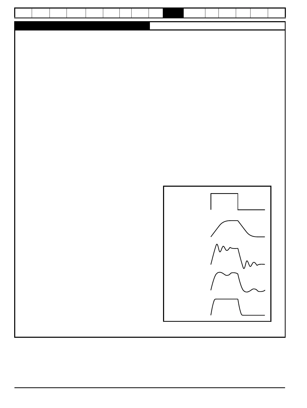
This involves the connecting of an oscilloscope to analog output 1 to
monitor the speed feedback.
Give the drive a step change in speed reference and monitor the
response of the drive on the oscilloscope.
The proportional gain (Kp) should be set up initially. The value
should be increased up to the point where the speed overshoots and
then reduced slightly.
The integral gain (Ki) should then be increased up to the point where
the speed becomes unstable and then reduced slightly.
It may now be possible to increase the proportional gain to a higher
value and the process should be repeated until the system response
matches the ideal response as shown.
The diagram shows the effect of incorrect P and I gain settings as
well as the ideal response.
2. Pr 3.17 = 1, Bandwidth set-up
If bandwidth based set-up is required, the drive can calculate Kp and
Ki if the following parameters are set up correctly:
Pr 3.20 - Required bandwidth,
Pr 3.21 - Required damping factor,
Pr 3.18 - Motor and load inertia. The drive can be made to
measure the motor and load inertia by performing an inertia
measurement autotune (see Autotune Pr 0.40, earlier in this
table).
3. Pr 3.17 = 2, Compliance angle set-up
If compliance angle based set-up is required, the drive can calculate
Kp and Ki if the following parameters are set up correctly:
Pr 3.19 - Required compliance angle,
Pr 3.21 - Required damping factor,
Pr 3.18 - Motor and load inertia The drive can be made to
measure the motor and load inertia by performing an inertia
measurement autotune (see Autotune Pr 0.40, earlier in this
table).
Speed demand
Insufficient proportional
gain [0.07]
Excessive proportional
gain [0.07]
Excessive integral gain
[0.08]
Ideal response

 Loading...


