Safety
Information
Introduction
Product
Information
System
configuration
Mechanical
Installation
Electrical
Installation
Getting
Started
Basic
parameters
Running
the motor
Optimization
SMARTCARD
operation
Onboard
PLC
Advanced
parameters
Technical
Data
Diagnostics
UL Listing
Information
Unidrive SPM User Guide 141
Issue Number: 3 www.controltechniques.com
10.1.3 Closed loop vector motor control
Pr 0.46 {5.07} Motor rated current Defines the maximum motor continuous current
The motor rated current parameter must be set to the maximum continuous current of the motor. (See section 10.2 Maximum motor rated current on
page 146, for information about setting this parameter higher than the maximum Heavy Duty current rating.) The motor rated current is used in the
following:
• Current limits (see section 10.3 Current limits on page 146, for more information)
• Motor thermal overload protection (see section 10.4 Motor thermal protection on page 146, for more information)
• Vector control algorithm
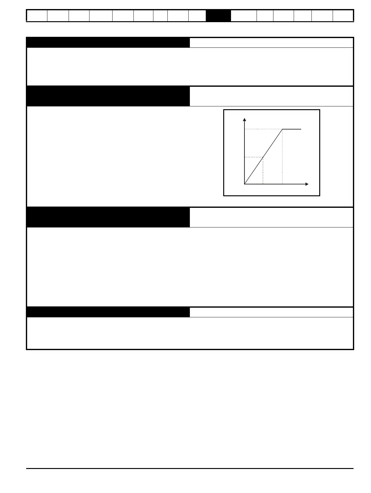
Pr 0.44 {5.09} Motor rated voltage Defines the voltage applied to the motor at rated frequency
Pr 0.47 {5.06} Motor rated frequency Defines the frequency at which rated voltage is applied
The motor rated voltage Pr 0.44 and the motor rated frequency Pr 0.47
are used to define the relationship between the voltage and frequency
applied to the motor, as shown.
The motor rated voltage is used by the field controller to limit the voltage
applied to the motor. Normally this is set to the nameplate value. To allow
current control to be maintained, it is necessary for the drive to leave
some 'headroom' between the motor terminal voltage and the maximum
available drive output voltage. For good transient performance at high
speed, the motor rated voltage should be set below 95% of the minimum
supply voltage to the drive.
The motor rated voltage and motor rated frequency are also used during
the rotating autotune test (see Autotune Pr 0.40 later in this table) and in
the calculations required for automatic optimization of the motor rated
speed (see Motor rated speed optimization Pr 5.16, later in this table).
Therefore, it is important that the correct value for motor rated voltage is
used.
Pr 0.45 {5.08} Motor rated speed Defines the full load rated speed of the motor
Pr 0.42 {5.11} Motor number of poles Defines the number of motor poles
The motor rated speed and motor rated frequency are used to determine the full load slip of the motor which is used by the vector control algorithm.
Incorrect setting of this parameter has the following effects:
• Reduced efficiency of motor operation
• Reduction of maximum torque available from the motor
• Reduced transient performance
• Inaccurate control of absolute torque in torque control modes
The nameplate value is normally the value for a hot motor; however, some adjustment may be required when the drive is commissioned if the
nameplate value is inaccurate. Either a fixed value can be entered in this parameter or an optimization system may be used to automatically adjust
this parameter (see Motor rated speed autotune Pr 5.16, later in this table).
When Pr 0.42 is set to ‘Auto’, the number of motor poles is automatically calculated from the motor rated frequency Pr 0.47, and the motor rated
speed Pr 0.45
Number of poles = 120 x (Motor rated frequency Pr 0.47 / Motor rated speed Pr 0.45) rounded to the nearest even number
Pr 0.43 {5.10} Motor rated power factor Defines the angle between the motor voltage and current
The power factor is the true power factor of the motor, i.e. the angle between the motor voltage and current. If the stator inductance is set to zero (Pr
5.25) then the power factor is used in conjunction with the motor rated current Pr 0.46 and other motor parameters to calculate the rated active and
magnetising currents of the motor, which are used in the vector control algorithm. If the stator inductance has a non-zero value this parameter is not
used by the drive, but is continuously written with a calculated value of power factor. The stator inductance can be measured by the drive by
performing a rotating autotune (see Autotune Pr 0.40, later in this table).
Output
voltage
Pr / 2
0.44
Pr
0.44
Pr / 2
0.47
Pr
0.47
Output
Output voltage characteristic

 Loading...


