Safety
Information
Introduction
Product
Information
System
configuration
Mechanical
Installation
Electrical
Installation
Getting
Started
Basic
parameters
Running
the motor
Optimization
SMARTCARD
operation
Onboard
PLC
Advanced
parameters
Technical
Data
Diagnostics
UL Listing
Information
Unidrive SPM User Guide 177
Issue Number: 3 www.controltechniques.com
**If output voltage from the encoder is >5V, then the termination resistors
must be disabled Pr 3.39 to 0.
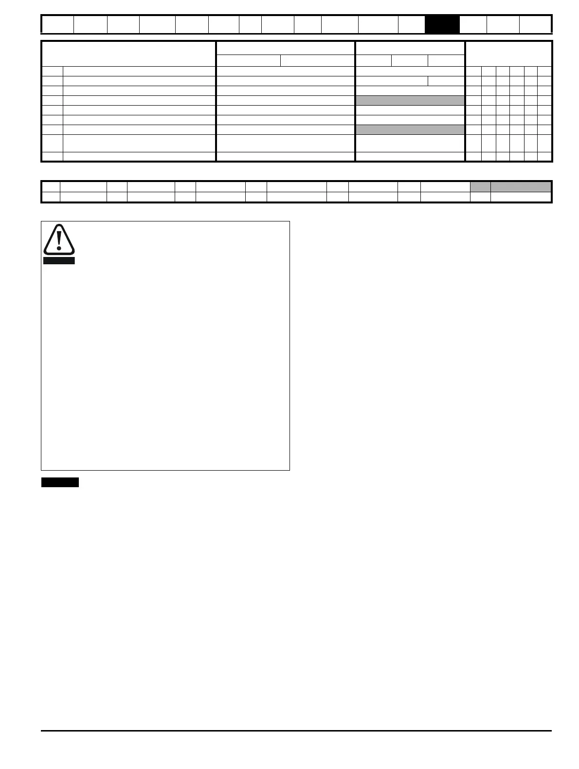
3.42 Drive encoder filter 0 (0), 1 (1), 2 (2), 4 (3), 8 (4), 16 (5) ms 0 RW Txt US
3.43 Maximum drive encoder reference 0 to 40,000 rpm 1500 3000 RW Uni US
3.44 Drive encoder reference scaling 0.000 to 4.000 1.000 RW Uni US
3.45 Drive encoder reference ±100.0%
RO Bi FI NC PT
3.46 Drive encoder reference destination Pr 0.00 to 21.50 Pr 0.00 RW Uni DE PT US
3.47 Re-initialise position feedback OFF (0) or On (1) OFF (0) RW Bit NC
3.48 Position feedback initialised OFF (0) or On (1)
RO Bit NC PT
3.49
Full motor object electronic nameplate
transfer
OFF (0) or On (1) OFF (0) RW Bit US
3.50 Position feedback lock OFF (0) or On (1) OFF (0) RW Bit NC
Parameter
Range(
Ú) Default(Ö)
Type
OL CL OL VT SV
RW Read / Write RO Read only Uni Unipolar Bi Bi-polar Bit Bit parameter Txt Text string
FI Filtered DE Destination NC Not copied RA Rating dependent PT Protected US User save PS Power down save
*Encoder phase angle (servo mode only)
With drive software version V01.08.00 onwards, the encoder
phase angles in Pr
3.25
and Pr
21.20
are copied to the
SMARTCARD when using any of the SMARTCARD transfer
methods.
With drive software version V01.05.00 to V01.07.01, the
encoder phase angles in Pr
3.25
and Pr
21.20
are only copied
to the SMARTCARD when using either Pr
0.30
set to Prog (2)
or Pr
xx.00
set to 3yyy.
This is useful when the SMARTCARD is used to back-up the
parameter set of a drive but caution should be used if the
SMARTCARD is used to transfer parameter sets between drives.
Unless the encoder phase angle of the servo motor connected
to the destination drive is known to be the same as the servo
motor connected to the source drive, an autotune should be
performed or the encoder phase angle should be entered
manually into Pr
3.25
(or Pr
21.20
). If the encoder phase angle
is incorrect the drive may lose control of the motor resulting in
an O.SPd or Enc10 trip when the drive is enabled.
With drive software version V01.04.00 and earlier, or when
using software version V01.05.00 to V01.07.01 and Pr
xx.00
set to 4yyy is used, then the encoder phase angles in Pr
3.25
and Pr
21.20
are not copied to the SMARTCARD. Therefore,
Pr
3.25
and Pr
21.20
in the destination would not be changed
during a transfer of this data block from the SMARTCARD.

 Loading...


