SS2100i-1 Gas Analyzer
B–8 4900002224 rev. E 12-18-20
2. Reconnect cables on the electronics assembly panel.
a. Slide the wire duct cover at the left of the enclosure towards the
top and connect the heater power terminal.
b. Connect the 24 VDC harness for the Watlow controller.
c. Connect the temperature/pressure cables by replacing the
green connector block.
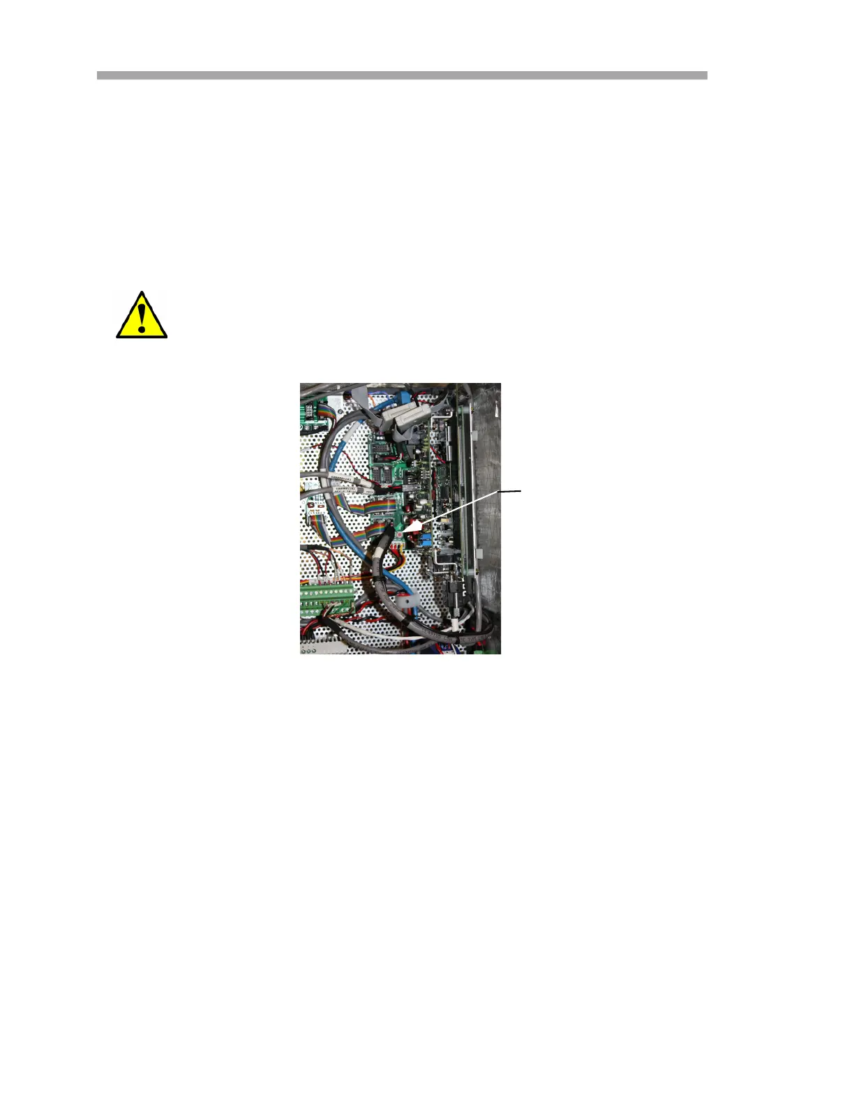
d. Connect the optical head cable to the backplane.
e. Replace the keypad and display control cable in the clips at the
top of the enclosure.
3. Close the enclosure cover.
4. Open the isolation valves to begin flow of process gas through the
analyzer.
5. Power up the analyzer (refer to the appropriate chapter in the
Firmware Manual for this analyzer for instructions).
The optical head cable connector will fit in several different
openings. Make sure the correct outlet is used. Refer to Figure
B–5 below.
OPTICAL HEAD
CABLE CONNECTION
Figure B–5 Optical head cable connection

 Loading...


