Maintenance 5. Arm #1
144 G10 / G20 Rev.20
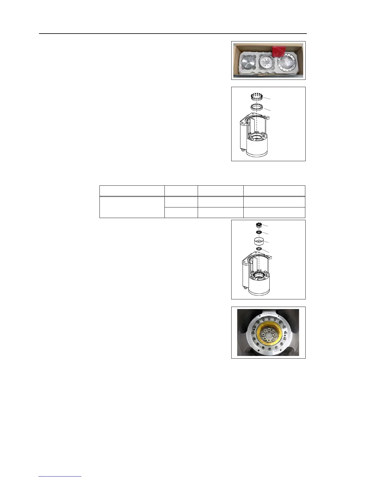
A new reduction gear unit contains the
in the picture on the right
Apply LOCTITE 241 on the screws.
the circular spline and the tap hole
grease (SK-1A) on the gear side of the
secure all bolts in a crisscross pattern so
secured evenly. Then, using a
tighten each bolt securely in a
pattern at the torque specified in the table
Item Bolt type Number of bolts Tightening torque
Joint #1 reduction gear unit
M5×25 16 10.0 N⋅m(101.9 kgf⋅cm)
M8×20 8
30.0 N⋅m(305.9 kgf⋅cm)
Apply LOCTITE 241 on the screws.
ring by aligning it with the tap hole.
on the gear side of the
flexspline.
Set the flexspline by aligning it with the tap hole.
the air vent of the spacer and
-1A) inside the flexspline.
Grease volume: 43 g
Apply grease to the bearing part of the waveform generator.
Execute steps from (2) to (
4) in Maintenance: 5.1 Replacing Joint #1 Motor.
Manipulator to the mounting position.
5) to (7) in Maintenance: 5.1 Replacing Joint #1 Motor.

 Loading...


