Maintenance 6. Arm #2
G10 / G20 Rev.20 149
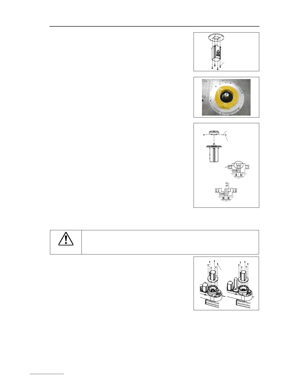
Joint #2 motor
Installation
Mount the motor flange on the Joint
Set the spring plate mounting hole of the motor
flange in the counter direction to the motor
cable.
Apply grease around the motor shaft.
Mount the waveform generator on
Be sure to fit the waveform
shaft edge. Tighten one of the set
flat face of the motor shaft until
just touches the surface. Insert a
into the other set screw hole to prevent
damage to the motor shaft.
For G10 series manipulator of
Put a space of 6.5 mm or less between the
waveform generator edge and the motor shaft
edge.
Put the end
faces together
See the figures above for the orientation of the waveform generator.
install the waveform generator properly.
Improper installation of the waveform
generator will result in improper function of
ount the Joint #2 motor unit on Arm #2.
If it is difficult to mount the motor, push it
moving Arm #2 slowly by hand.
At this point, be careful about the direction of
the spring plate mounting hole of
is for the Radiating Unit.
Mount the radiating unit to the motor using insulation lock tie. Then, secure the
mounting bolt of head sink pipe beneath the arm. To do so, be careful not to move
the plate.
For details, refer to Maintenance 13. Radiating Unit.

 Loading...


