EasyManuals Logo
Home>Epson>Robotics>G20 Series

Epson G20 Series User Manual

Epson G20 Series
252 pages
To Next Page IconTo Next Page
To Previous Page IconTo Previous Page
Page #164 background imageLoading...
Page #164 background image
Maintenance 6. Arm #2
152 G10 / G20 Rev.20
Joint #2
reduction gear
unit
Removal
(1)
Turn ON the Controller.
(2)
Push down the shaft to its lower limit while pressing the brake release switch. Be
sure to keep enough space and prevent the
end effector
hitting any peripheral
equipment.
The brake release switch is applied to both Joints #3 and #4. When the brake release
switch is pressed, the respective brakes of the Joints #3 and #4 are released
simultaneously.
Be careful of the
shaft falling and rotating while the brake release switch is
being
pressed
because the shaft may be lowered by the weight of an end effector.
(3)
Turn OFF the Controller.
(4)
Execute steps from (1) to (9) in
Maintenance: 6.1 Replacing Joint #2 Motor
and
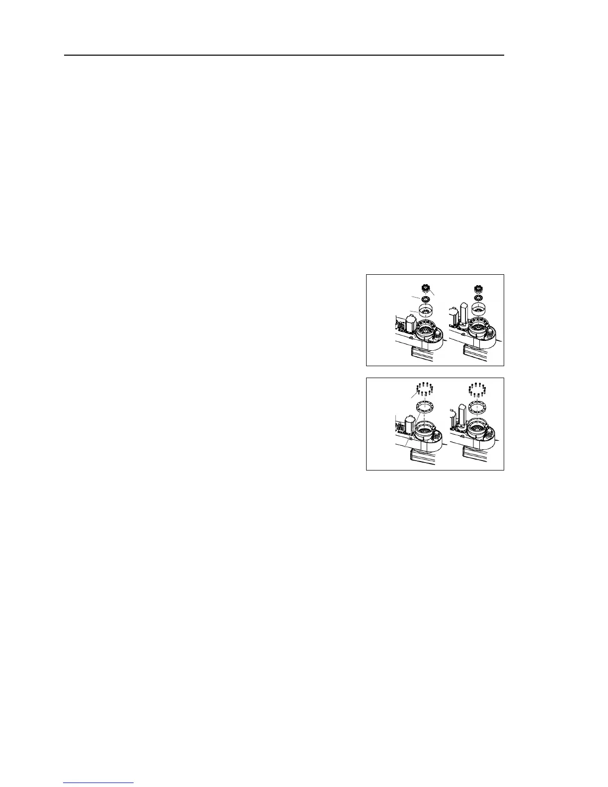
remove the waveform generator from the Joint #2 motor.
(5)
Use the extracting M5 screws and remove the
flexspline from Arm #2.
8-M8×20
G10
G20
Flexspline
Spacer
(6)
Remove the circular spline from Arm #2.
16-M5×25
G10
G20
Circular
spline

Table of Contents

Questions and Answers:

Question and Answer IconNeed help?

Do you have a question about the Epson G20 Series and is the answer not in the manual?

Epson G20 Series Specifications

General IconGeneral
BrandEpson
ModelG20 Series
CategoryRobotics
LanguageEnglish

Related product manuals