Maintenance 6. Arm #2
G10 / G20 Rev.20 153
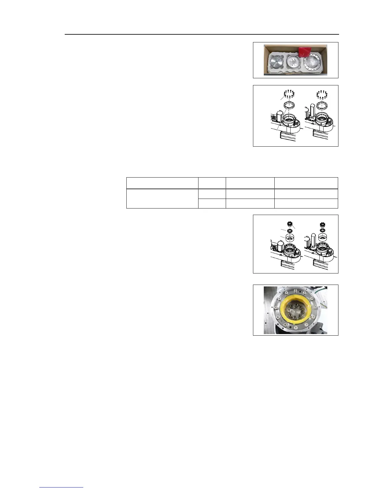
A new reduction gear unit contains the
shown in the picture on the right
the circular spline and the tap
grease (SK-1A) on the gear side of the
secure all bolts in a crisscross pattern so
that the bolts will be secured
tighten each bolt securely in a
pattern at the torque specified in the
Item Bolt type Number of bolts Tightening torque
Joint #2 reduction gear unit
M5×25
16
10.0 N⋅m (102 kgf⋅cm)
M8×20
8
30.0 N⋅m (306 kgf⋅cm)
-1A) on the flexspline teeth.
flexspline by aligning it with the tap hole.
Aligning the tap hole and mount the flexspline.
the air vent of the spacer.
align the position, move Arm
-1A) inside the flexspline.
Grease volume 43 g
Apply grease to the bearing part of the waveform generator.
Execute steps from (2) to (9) in
Maintenance: 6.1 Replacing Joint #2 Motor.
 Loading...


