Maintenance 7. Arm #3
162 G10 / G20 Rev.20
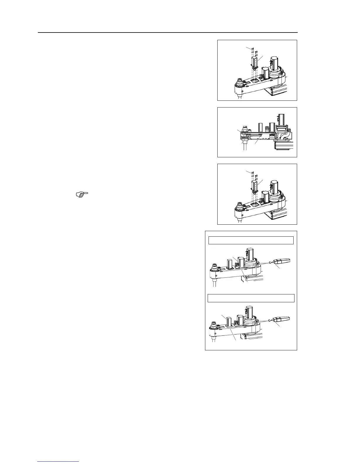
Joint #4 motor unit in Arm #2 so that
the motor cable faces toward the
The screws are not secured in this step.
U belt around the U1 pulley and the
2 pulley so that the gear grooves of the belt
are fit into those of the pulleys
Loosely secure the Joint #4 motor unit to Arm
#2.
Loosely secure the Joint #4 motor unit to Arm
#2
so that the motor unit can be moved by hand,
it will not tilt when pulled. If the unit is
too loose or too tight, the belt will not
Apply the proper tension to the Z belt and
U belt, and then secure the Joint #3 motor
unit and Joint #4 motor unit.
a suitable cord or string
around the motor unit near its mounting
plate
. Then, pull the cord using a force
or similar tool to apply the specified
tension shown in the figure on the right
Make sure that the brake cables do not
touch the pulley.
G10 : Z belt tension = 130 N (13.3 kgf)
G10 :
U belt tension = 160 N
(16.3 kgf)

 Loading...


