Maintenance 8. Arm #4
182 G10 / G20 Rev.20
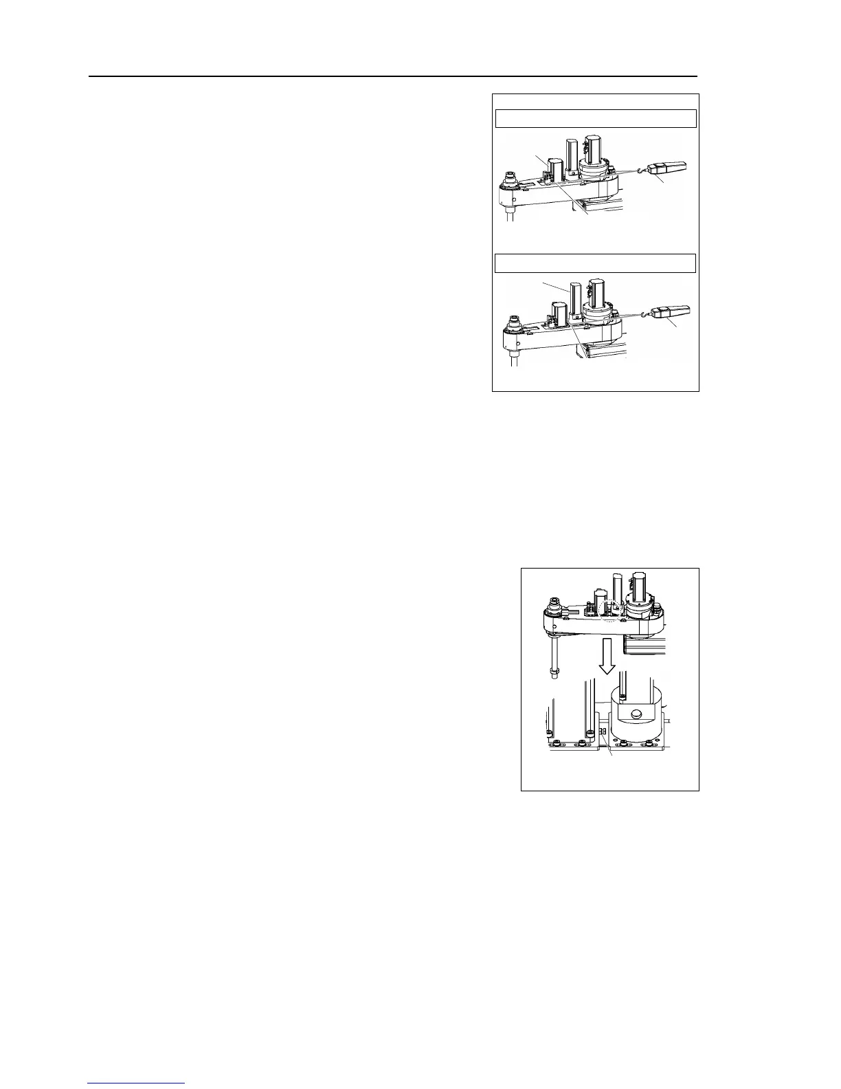
Apply the proper tension to the Z belt and U
b
elt, and then secure the Joint #3 motor unit
a suitable cord or string around
each motor unit near its mounting plate
ull the cord using a force gauge or
similar tool to apply the specified tension
shown in
Make sure that the brake cables do not touch
the pulley.
G20 : Z belt tension = 130 N (13.3 kgf)
G20 : U belt tension = 200 N (20.4 kgf)
How to apply the proper tension to the U belt of G20
There is a bolt on the Z axis plate part to apply tension to the U belt.
(Since it is difficult to apply 200N tension on the U belt only by human power.)
The procedure to apply tension using the bolt is as follows.
We recommend the Tensometer
U series from Gates Unitta for measuring the belt
tension.
Weight 5.25 g/m Width 20 mm Span 297.5 mm
1. Loosen the nut.
Be careful about the motor flange.
It may break with too much power.
2. Screw the bolt and push in the U axis plate.
3. Use the ultrasonic gauge to apply the proper
tension to the U axis belt.
4. Secure the U axis unit.
5. Place back the bolt to the position.
Secure the nut.
6. Loosen the nut.
G20: U belt tension
Bolt + nut for adjustment (M4)

 Loading...


