Maintenance 10. Ball Screw Spline Unit
G10 / G20 Rev.20 201
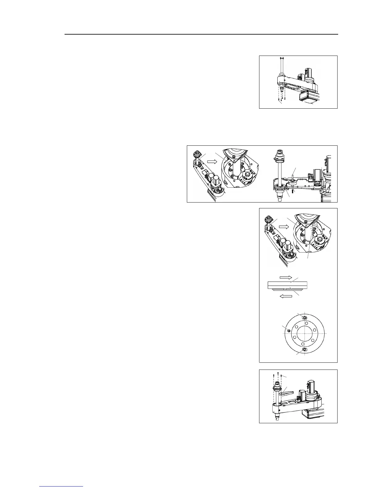
Pass the Z belt through the shaft and mount the ball screw spline unit to Arm #2.
Secure the nut mounting screws of the ball screw
spline shaft on
Be sure to keep the timing belt from being stuck
between the nut and Arm #2.
Mount the Joint #4 intermediate pulley.
Place the M4 bolt position of the Z axis gear to the end of
Insert the intermediate pulley from the lower side
of Arm #2 and engage the gear.
The gear for Z axis is a backlash
keep the gear and pinion engage.
If the gear is out of joint
1. Rotate the main gear and the assist gear in
the opposite direction and shift one tooth of
the gear. (The pin pushes the spring and
generates pressure.)
2. Use the tap to mount the M4 bolt.
3. Make sure that the pin position of the main
gear is near the center of the slotted hole.
Hold the spline plate and place the U belt to the U2
pulley.

 Loading...


