Maintenance 10. Ball Screw Spline Unit
G10 / G20 Rev.20 203
U belt around the U1 pulley and the U2
pulley so that the gear grooves of
into those of the pulleys
Loosely secure the Joint #4 motor unit to Arm
Loosely secure the Joint #4 motor unit to Arm
the motor unit can be moved by hand, and
will not tilt when pulled. If the unit is secured
or too tight, the belt will not have the
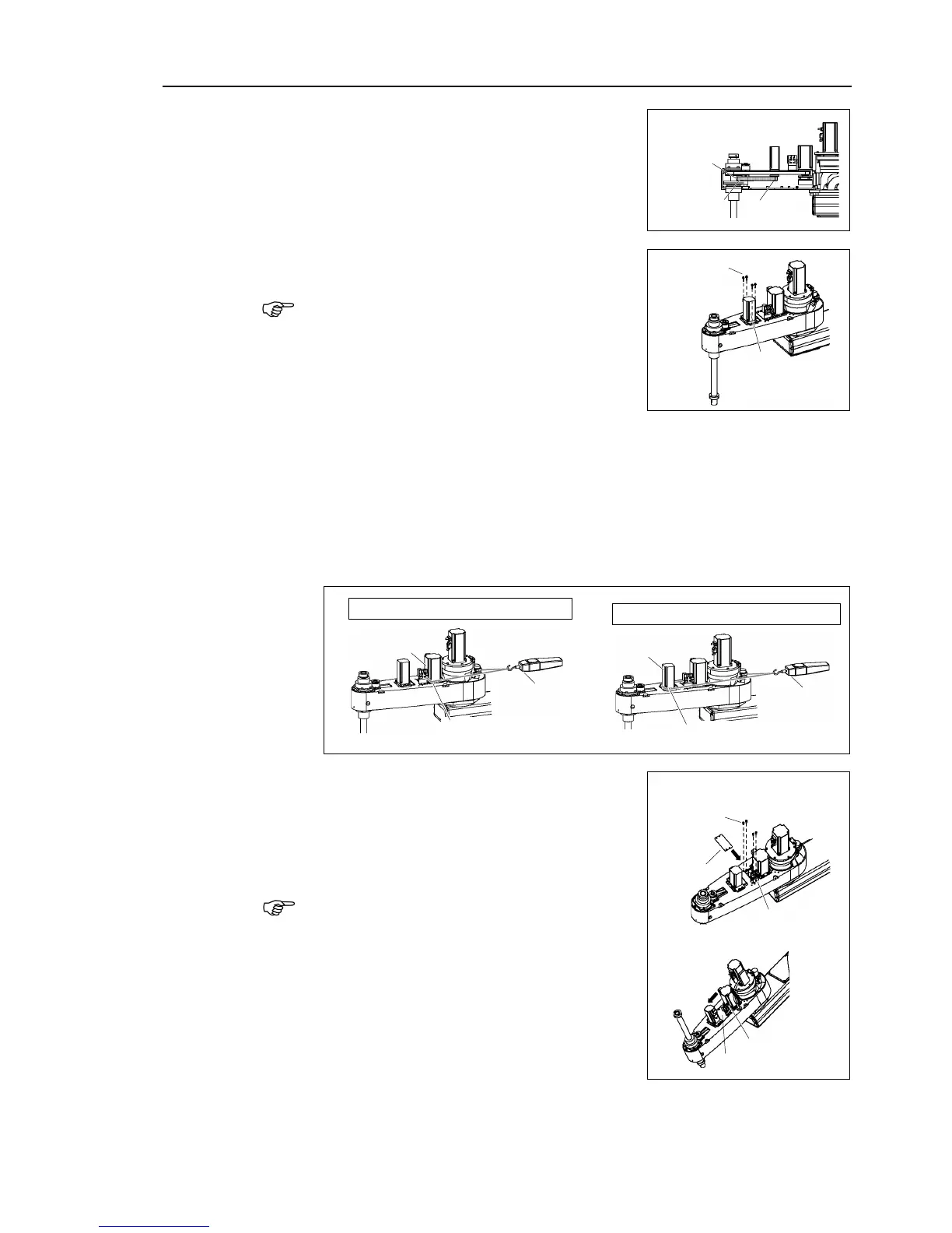
Apply the proper tension to the Z belt and U belt, and then secure the Joint #3
motor unit and Joint #4 motor unit.
a suitable cord or string around the motor unit near its mounting
. Then, pull the cord using a force gauge or similar tool to apply the
specified tension shown in the figure on the right
Make sure that the brake cables do not touch the pulley.
G10 : Z belt tension = 130 N (13.3 kgf)
G10 : U belt tension = 160 N (16.3 kgf)
When you use the plate of
ount the plate without pressing it to the Joint #4
When you use the plate of
the plate with pressing it to the motor.
When mounting the battery unit, be sure to keep
the connectors connected to the battery unit.
If connectors of the battery unity are
disconnected, you need to perform calibration
again.

 Loading...


