Maintenance 14. Calibration
G10 / G20 Rev.20 223
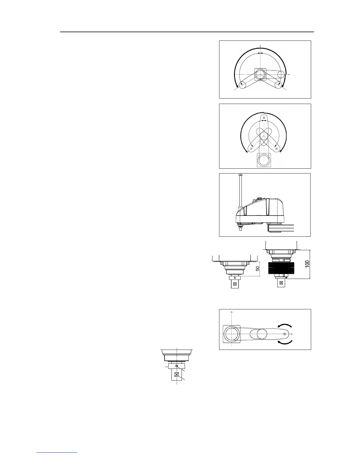
0 pulse position of Joint #1:
position aligned with X-axis in
Robot coordinate system
0 pulse position of Joint #2:
position where Arms #1 and #2
are in a straight line
(Regardless of the Joint #1
0 pulse position of Joint #3:
upper limit position in motion
range
The height of Joint #3 depends
on manipulator model.
0 pulse position of Joint #4:
position where the flat surface
(or screw hole 1) on the shaft
faces toward the tip of Arm #2
Screw hole 1 and flat surface are located
in the center of the shaft.
hole 1 and 2 are located at right
 Loading...


