Functions 13. I/O Connector
148 RC700 Series Rev.3
13.2 Output Circuit
Rated Output Voltage : +12 V to 24 V ±10%
Maximum Output Current : TYP 100 mA/1 output
Output Driver : PhotoMOS Relay
On-State Resistance (average) : 23.5 Ω or less
Two types of wiring are available for use with the nonpolar PhotoMOS relay in the output
circuit.
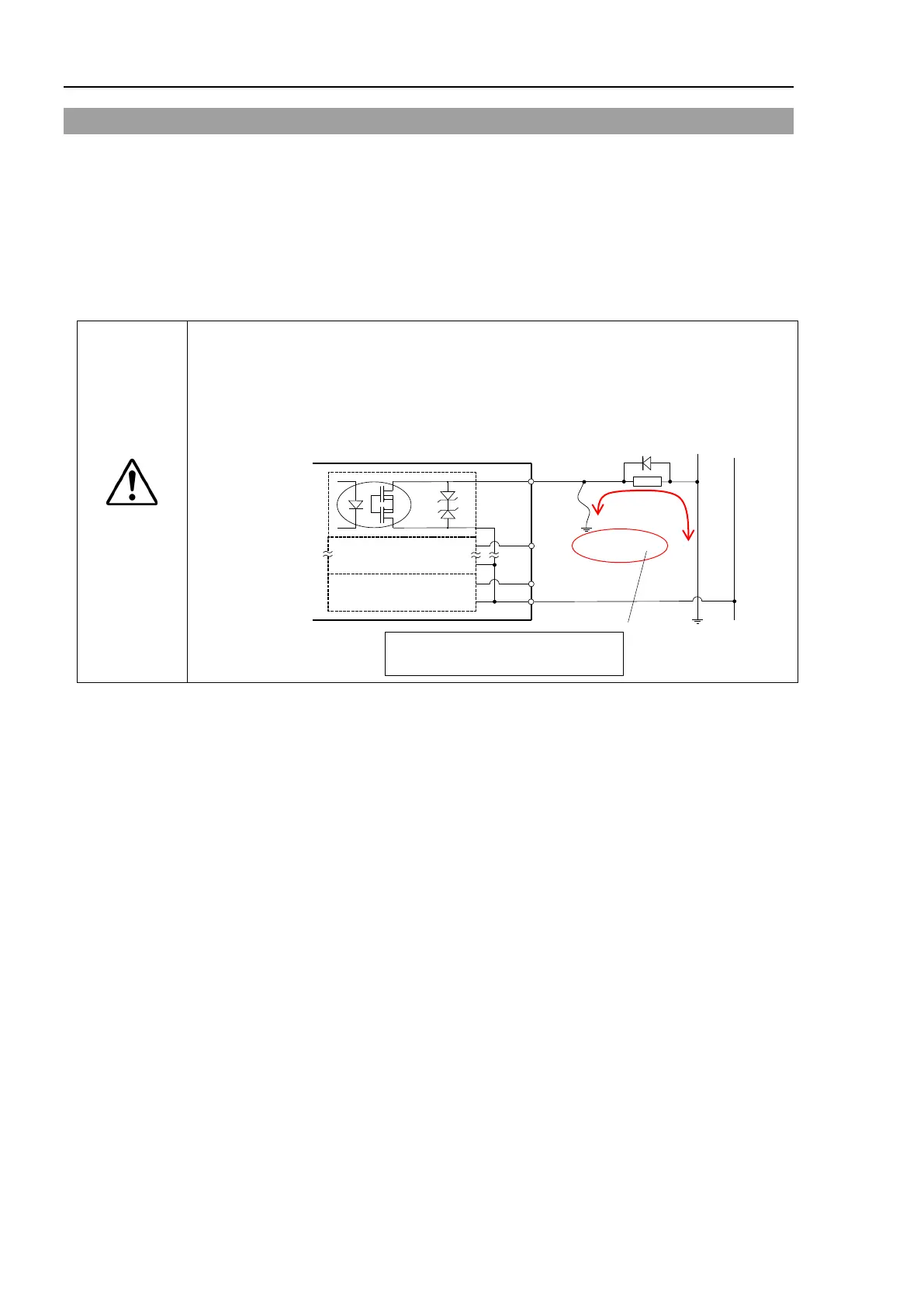
CAUTION
Use Plus Common (PNP) to prevent the load from operating unintentionally if the
wiring between the controller and the load is
grounded fault. This conforms to
European Machinery Directives.
If there is ground fault, it
does not flow to
the load and does not start operate.
Plus Common (PNP) connection

 Loading...


