Functions 14. I/O Remote Settings
RC700 Series Rev.3 161
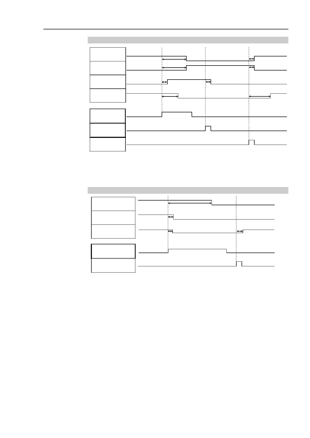
14.2.4 Timing Diagram for Safety Door Input Sequence
[Unit: msec]
(*1) A logical signal to explain the timing of internal processing of the controller.
For details about input signals name and operating conditions, refer to the 11.3 Pin
Assignments.
14.2.5 Timing Diagram for Emergency Stop Sequence
Running
MotorsOn
EStopOff
ESW Signal
Reset Signal
[Unit: msec]
(*1) A logical signal to explain the timing of internal processing of the controller.
For details about input signals name and operating conditions, refer to the 11.3 Pin
Assignments.

 Loading...


