EasyManuals Logo

Epson RC700 Series Original Instructions

Epson RC700 Series
228 pages
To Next Page IconTo Next Page
To Previous Page IconTo Previous Page
Page #186 background imageLoading...
Page #186 background image
Functions 16. Option Slots
168 RC700 Series Rev.3
16.2.4 Input Circuit
Input Voltage Range
: + 12 V to 24 V ±10%
ON Voltage : + 10.8 V (Min.)
OFF Voltage : + 5 V (Max.)
Input Current : 10 mA (TYP) at + 24 V input
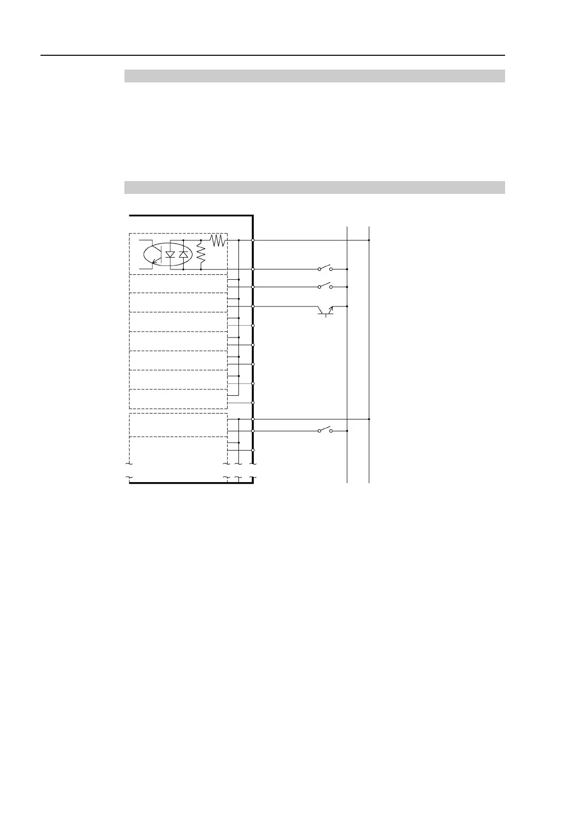
Two types of wiring are available for use with the two-way photo coupler in the input circuit.
Protected Expansion I/O Board Typical Input Circuit Application 1
1 Input No.64 to 71 common
2 Input No.64
3 Input No.65
4 Input No.66
5 Input No.67
6 Input No.68
7
Input No.69
8
Input No.70
9 Input No.71
Expansion I/O board-1
(Same)
Omit
GND +DC
18 Input No.72 to 79 common
19 Input No.72
20 Input No.73
(Same)
(Same)
(Same)
(Same)
(Same)
(Same)
(Same)

Table of Contents

Other manuals for Epson RC700 Series

Questions and Answers:

Question and Answer IconNeed help?

Do you have a question about the Epson RC700 Series and is the answer not in the manual?

Epson RC700 Series Specifications

General IconGeneral
ModelRC700 series
CategoryController
Programming LanguageSPEL+
Safety StandardISO 10218-1
TypeRobot Controller
Communication InterfaceEthernet, RS-232, USB
Operating Temperature0°C to 45°C (32°F to 113°F)
Humidity20% to 80% (non-condensing)
Number of controllable robots4

Related product manuals