Functions 16. Option Slots
RC700 Series Rev.3 193
EUROMAP connecter
(CN4) Pin No.
Signal Name Note
A4
Reserved for future use by EUROMAP
A5
Not fixed by EUROMAP, manufacturer
dependent
I/O Input (*1)
Reserved for future use by EUROMAP
A9 Supply from IMM
(*1)
Enable movement of core pullers 1 to position 1
Enable movement of core pullers 1 to position 2
Enable movement of core pullers 2 to position 1
Enable movement of core pullers 2 to position 2
C5
Not fixed by EUROMAP, manufacturer
dependent
I/O Input (*1)
Reserved for future use by EUROMAP
Reserved for future use by EUROMAP
C8
Not fixed by EUROMAP, manufacturer
dependent
I/O Input (*1)
*1: DO NOT input a voltage which exceeds 24V. Board may get damage and burnout.
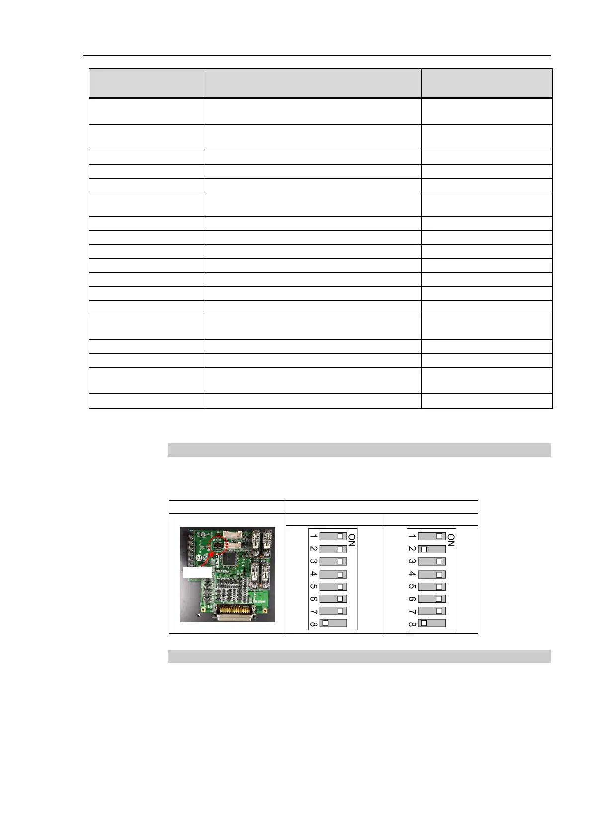
16.8.2 Board Settings (EUROMAP67 Board)
Configure DIP-Switch (SW1) to enable the robot Controller to recognize the
EUROMAP67 board.
Switch setting: Setup the DSW1
16.8.3 Installation (EUROMAP67 Board)
For the install procedure, refer to the RC700 series Maintenance Manual.

 Loading...


