EPSON Stylus COLOR 670 Revision A
Disassembly and Assembly Disassembly 89
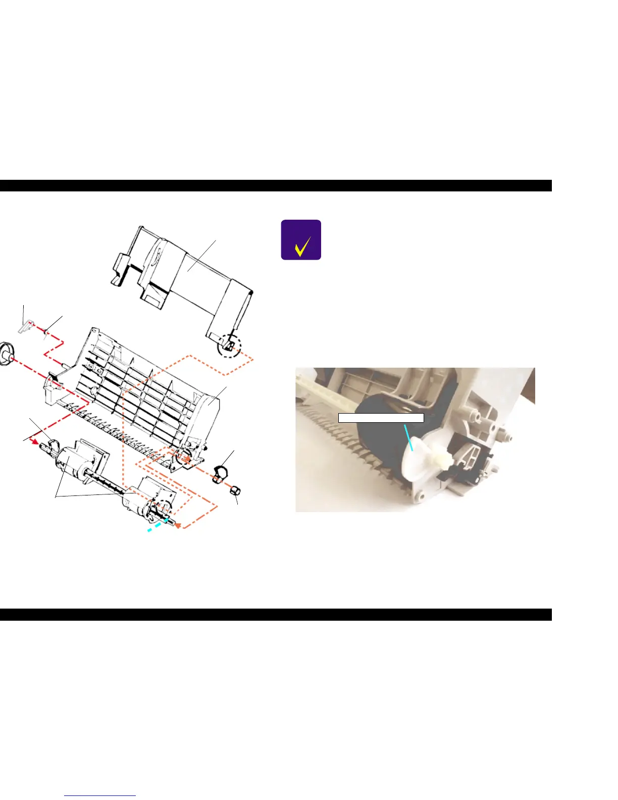
The following is the ASF Assembly exploded diagram.
Figure 4-30. ASF Disassembly
Figure 4-31. Hopper Release Lever Installation Direction
Hopper Assembly
Torsion Spring 41.2
Brake Lever
(White)
(Black)
LD Roller Assembly
Right Hopper
Release Lever
ASF Frame
Left Hopper Lever
LD Roller Shaft
Right LD Roller
Fixing Bushing
CHECK
POINT
n During disassembly and assembly of the ASF Hopper
Assembly, do not let the grease on the cam parts touch
other parts. Wipe off any grease smeared on other parts.
n Be careful of the direction of the Hopper Release Lever
when installing it. (Refer to Figure 4-31.)
n Make sure the LD Roller Assembly is installed firmly to the
rail of the ASF Frame. (Refer to Figure 4-32.)
n Make sure the Left Frame of the left LD Roller Assembly is
set to the cutoff of the Paper Edge Guide. (Refer to Figure
4-33.)
n When installing the right and left LD Roller Fixing
Bushings, make sure the bushings are firmly installed and
do not slip off. Also, make sure the Black LD Roller
Assembly goes on the right side of the shaft. (Refer to
Figure 4-31 below.)
Right Hopper Release Lever
 Loading...


