Appendix D-22 Product Overview Rev. A
Confidential
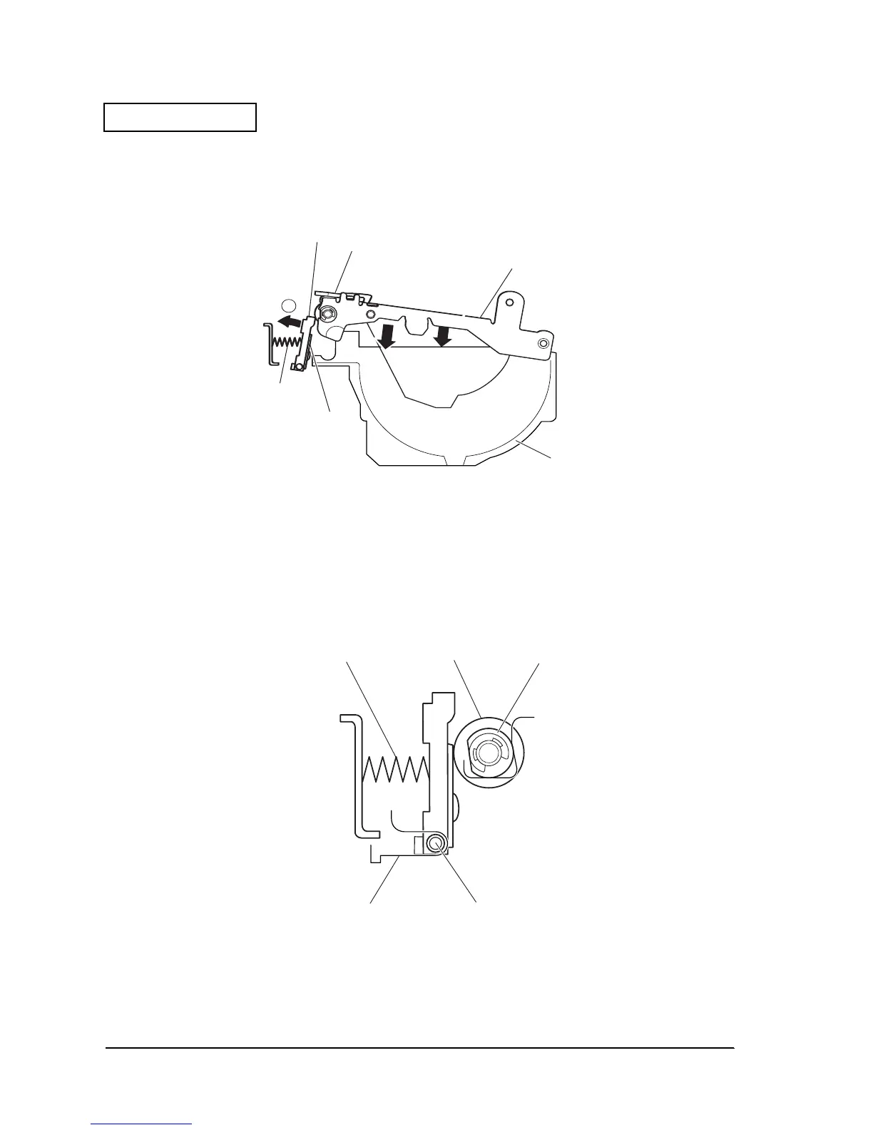
When the frame cover is closed, the top of the thermal head radiation plate and platen first make
contact as shown in the figure below, and the thermal head separates from the links in the
direction indicated by arrow ➂, causing the head chip of the thermal head to make contact with
the platen.
Figure D-29
The force of the thermal head against the platen acts as a downward force on the frame cover,
fixing the platen bearings to the positioning grooves provided in the left and right frames. The
grooves that support the thermal head support shafts are open to the rear surface of the head,
allowing the thermal head to move along the platen. Uniform force acts in the thermal head
print line direction.
Figure D-30
Heat slinger
Platen
Frame cover
Paper holder
Head chip
Head press spring
3
Head press spring Platen Platen shaft holder
Thermal head shaft
Right frame
(Left frame)
 Loading...


