Rev. A Disassembly and Assembly 2-19
Confidential
TM-H6000/H6000P Service Manual
Note:
Check that the soldering is secure.
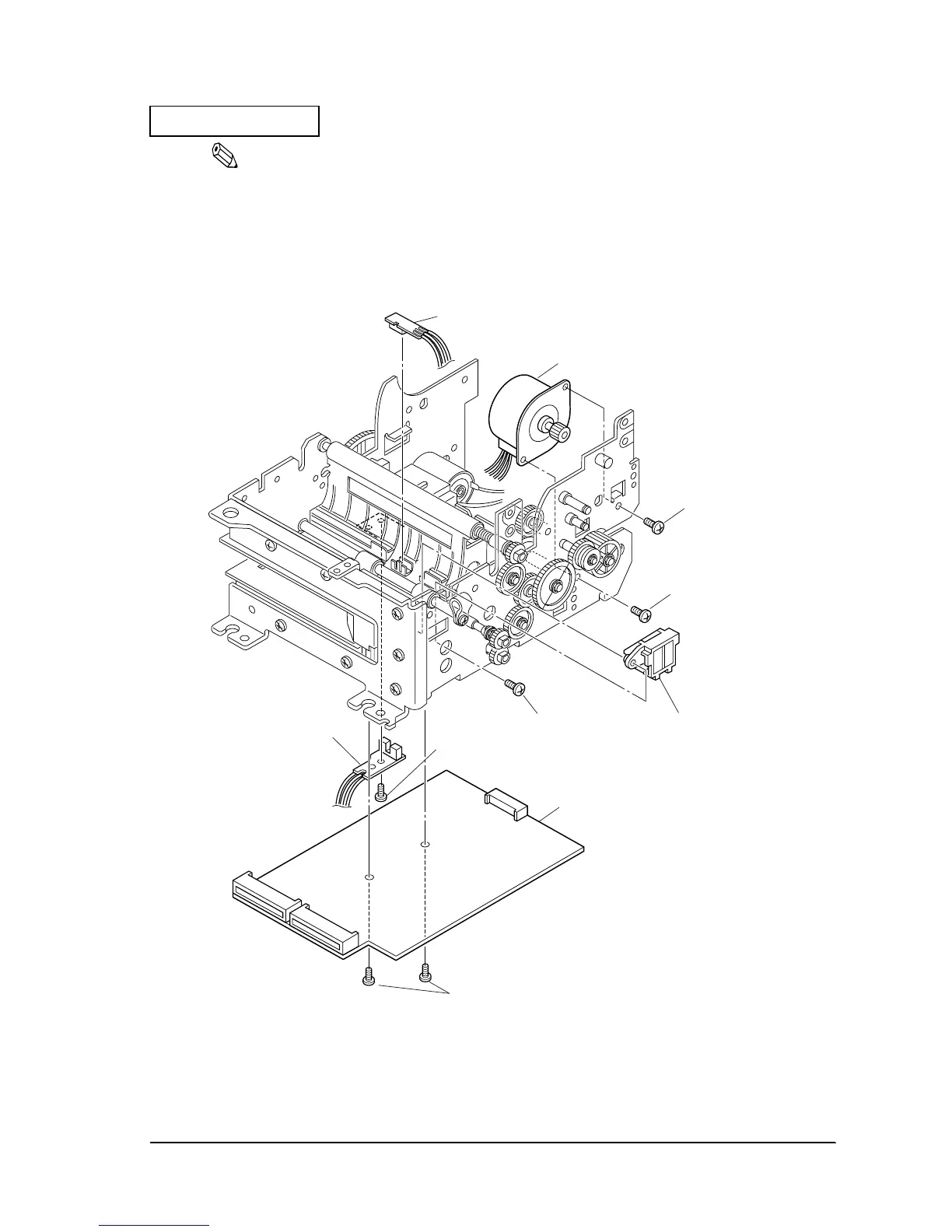
55. Insert the wiring.
56. Affix the R cover detector cable assembly to the main circuit board with adhesive tape.
57. Attach the MICR plate shutter to the slip guide lower frame (type B) with one screw.
Figure 2-16
691
screw(C.B.S-tite F,3X6)
691
screw(C.B.S-tite F,3X6)
722
screw(C.B.P-tite,3X8)
672
Lever motor T.P. detector
assembly
653
MICR shutter
691
screw(C.B.S-tite F,3X6)
691
screw(C.B.S-tite F,3X6)
704 Paper feed motor
673
Main circuit board assembly
(for M-U675)
671
Slip T.O.F. detector assembly
 Loading...


