Disassembly and Assembly 2-20 Rev. A
Confidential
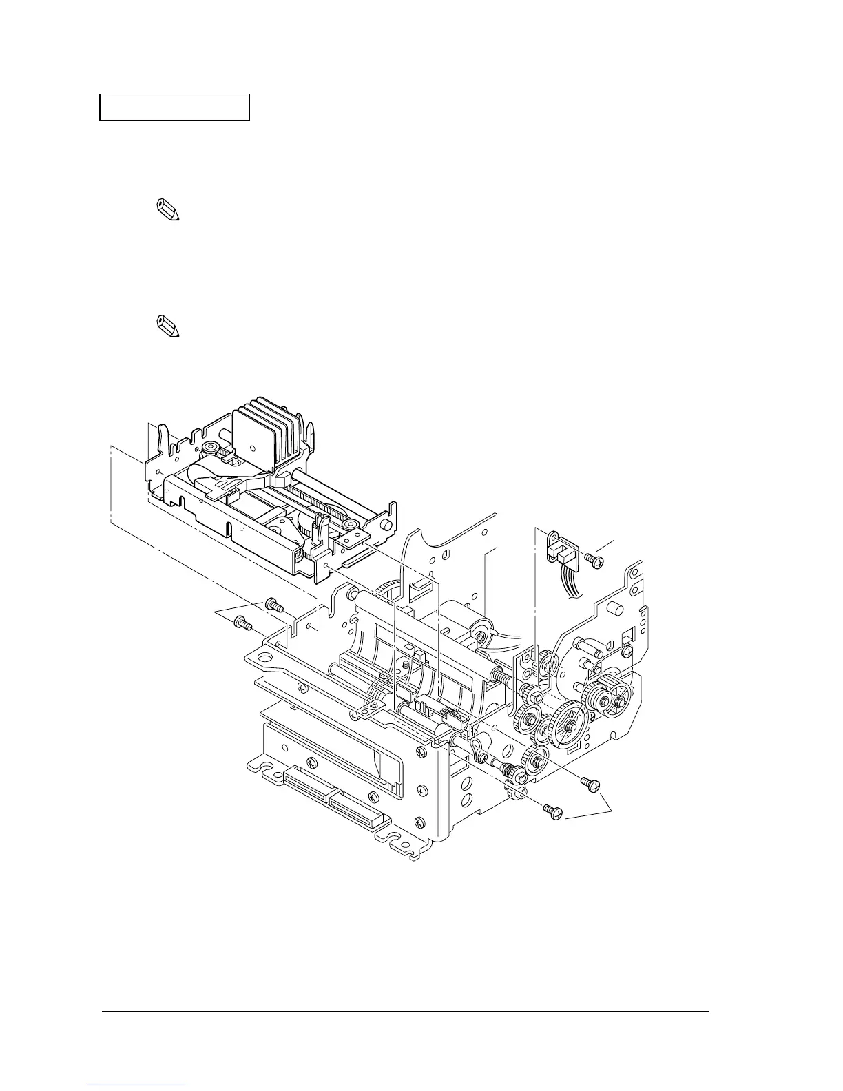
58. Using four screws, attach the carriage frame unit to the main frame sub assembly. Pass the
intermediate cable through the hexagonal hole in the main sub assembly frame, and pull out
enough cable. Fit the nibs in the carriage frame unit in the main frame notches.
Note:
Check the operating status of the ribbon drive plate assembly.
59. Allign and attach- the front cover detector assembly to the main sub assembly frame nibs.
60. Solder the lead wire of the front cover detector assembly to the main circuit board.
Note:
Check that the soldering is secure.
61. Install the wiring.
Figure 2-17
730
screw
(C.B.S-tite F,3X4)
691
screw
(C.B.S-tite F,3X6)
691
screw
(C.B.S-tite F,3X6)
 Loading...


