Disassembly and Assembly 2-28 Rev. A
Confidential
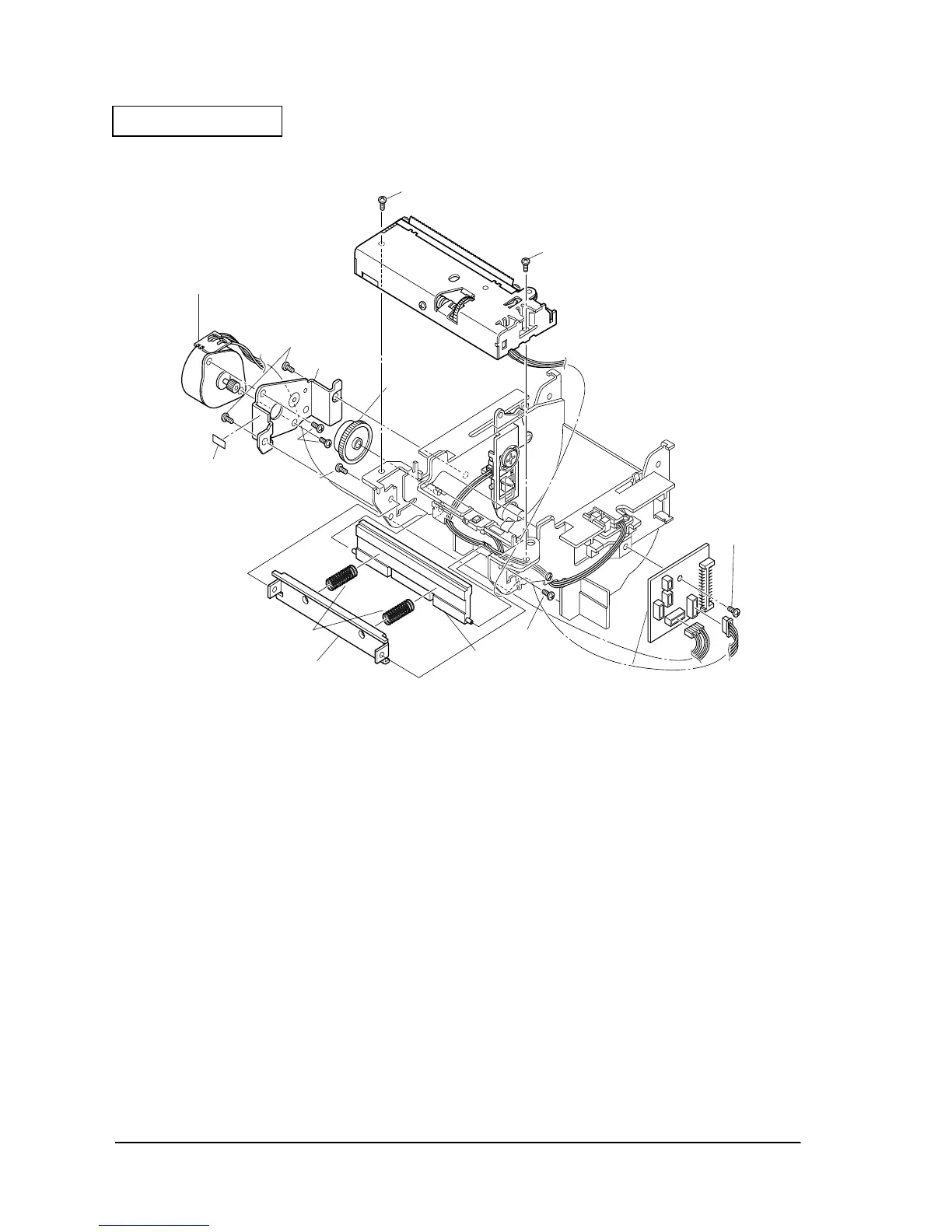
17. Install the autocutter unit with two screws.
Figure 2-24
18. Insert the platen into the platen assembly bearing and attach to the cover frame with one
E-ring.
19. Attach the cover frame to the left and right frames with two E-rings. Insert the cover
rotation shaft from the left and right frame covers, and tighten.
20. Hook the cover springs to the left and right frames. Check the direction for mounting the
cover springs.
21. Attach the fixed blade holder spring to the cover frame.
22. Attach the fixed blade to the cover frame.
23. Connect the N. E. detector lead wire to the micro switch.
24. Connect the cover open detector lead wire to the circuit board assembly sensor A.
25. Affix head caution label B to the front of the paper holder and the front of the motor frame.
540
screw(C.B.S-tite F,3X6)
540
screw(C.B.S-tite F,3X6)
544
Receipt paper feed motor
513
Head caution seal
540
505
Deceleration gear
519
Pressurizing plate
506
Press head spring
540
screw(C.B.S-tite F,3X6)
525
Thermal print head assembly
516
Motor frame
546
Paper cutter cover assembly
540
screw(C.B.S-tite F,3X6)
540
screw(C.B.S-tite F,3X6)
527
Intermit circuit board
assembly
 Loading...


