Rev. A Disassembly and Assembly 2-31
Confidential
TM-H6000/H6000P Service Manual
14. Connect the control panel cable to the control panel circuit board assembly.
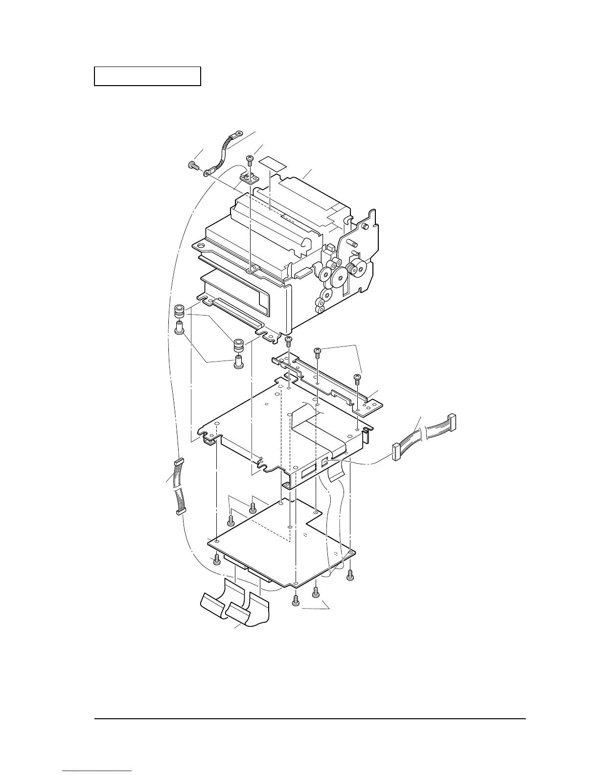
Figure 2-27
101 screw(C.B.S-tite F,3X4)
203 Earth wire assembly
107
screw
(C.P.S-tite(0),3X6)
208
Switch panel circuit board
assembly
210
113
Rubber
insulator spacer
106 screw(C.B.S-tite F,3X6)
107
screw
(C.P.S-tite(0),3X6)
107
screw(C.P.S-tite(0),3X6)
107
screw(C.P.S-tite(0),3X6)
128 Strengthening plate
114
Metallic insulator spacer
600 Mechanism assembly
(M-U675, type AB)
206
Intermit circuit board
cable
201
Main circuit board assembly
(for TM-H6000/H6000P)
209 Circuit board FFC
 Loading...


