100i / 200i / 300i / 400i
32 INSTALLATION Manual PN: 0560956430
Cooling System Requirements
Coolant must be added to the system on installation. The amount required varies with torch leads length.
ESAB recommends the use of its coolants 7-3580 and 7-3581 (for low temperatures).
Coolant Capabilities
Cat. Number and Mixture Mixture Protects To
7-3580 ‘Extra-Cool™’ 25 / 75 10° F / -12° C
7-3581 ‘Ultra-Cool™’ 50 / 50 -27° F / -33° C
7-3582 ‘Extreme Cool™’ Concentrate* -76° F / -60° C
* For mixing with D-I Cool™ 7-3583
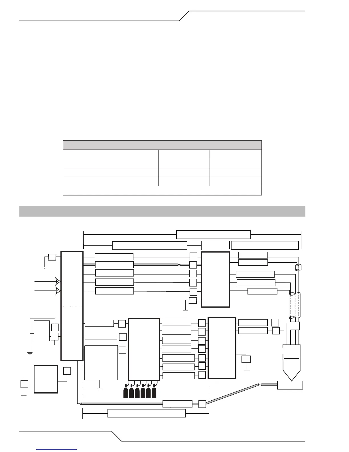
3.02 System Layout 100i - 200i Amp
Refer to section 3.08 and 3.10 for ground connections and ground cables.
Primary power
Work
CNC
Remote
Arc
Starter
Art # A-11995
Torch
Coolant Supply
Coolant Return
Control Cable
Pilot Return
Coolant Supply
Coolant Return
Plasma Gas
Shield Gas
Work Cable
DMC-3000
Gas
Console
Ultra-Cut
Power
Supply
DPC-3000
Gas
Control
Positioning Tube
Plasma Gas
Marking
Shield
Shield Gas
Negative
Pilot Return
Control Cable
100’ / 30.5 m Maximum Length
Shield
H
Q
R
U
S
A
B
C
D
E
P
K
L
O
I
J
G
175’ / 53.3 m Maximum Length
Preflow
Fiber Optic
L
Water Shield
T
125’ / 38.1 m Maximum Length
175’ / 53.3 m Maximum Length
Fiber Optic
Control Cable
F
Touch
Screen
Controller
V
W
F1
F1
F
F
Ground Cable
to PS Only
When DMC
Mounted On
Top Of PS
-If not - Earth-
Gas Supply
The customer must supply all gases and pressure regulators. Gases must be of high quality. Pressure regulators must
be double-stage and installed as close as possible to the gas console. Contaminated gas can cause one or more of the
following problems:
• Reduced cutting speed
• Poor cut quality
• Poor cutting precision
• Reduced consumables life.
• Oil or grease contamination from compressed or bottled air can cause fires in conjunction with oxygen.