Home
ESAB
Welding System
100i
Page 107 (Automated Gas Control System Replacement Components)
ESAB 100i - Automated Gas Control System Replacement Components
254 pages
Manual
Save Page as PDF
To Next Page
To Next Page
To Previous Page
To Previous Page
Loading...
100i / 200i / 300i / 400i
Manual PN: 0560956430
P
AR
TS LISTS
107
6.12
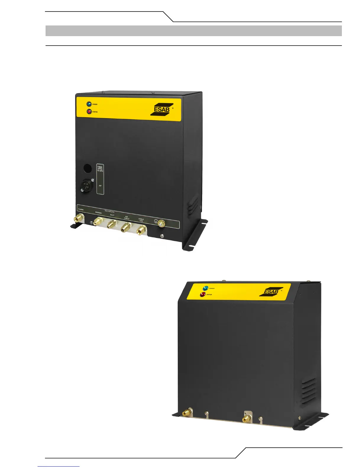
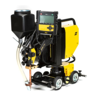
Automated Gas Control System Replacement Components
Item #
Qty
Description
Catalog #
1
1
Assy
, Gas Selection Console
0559099491
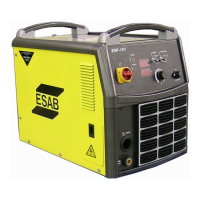
2
1
Assy
, Gas Control Unit
0559099443
106
108
Table of Contents
Main Page
Default Chapter
4
User Responsibility
4
Table of Contents
7
Section 1: Safety
11
Safety Precautions - ENGLISH
11
Précautions de Sécurité - FRENCH CANADIAN
16
Section 2: Specifications
21
General Description of the System
21
Plasma Power Supply
21
Remote Arc Starter
21
Gas Control Module
21
Precision Plasma Cutting Torch
21
Specifications & Electrical Requirements
22
Power Supply Dimensions
24
Power Supply Rear Panel Features
25
Gas Requirements
26
Gas Applications
28
Torch Specifications
29
Section 3: Installation
31
Installation Requirements
31
System Layout 100I - 200I Amp
32
System Layout 300I Amp
33
System Layout 400I Amp
33
Recommended Gas Supply Hose
34
Leads and Cables All Amperage
34
Lift the Power Supply
35
Connect Input Power and Ground Cables
36
Connect Work Cable and Pilot and Negative Leads
37
Ground Connections
38
Connect Coolant Leads
41
Connect Cables for CNC, Remote Arc Starter, Gas Selection, and Heat Exchanger
42
Handling and Installation of Fiber Optics
43
Correct Installation
44
Connect Cable and Gas Section Console Fiber Optic Cable to CCM
47
Set Switches on the Command - Control Module
49
Height Control Connections
51
Gas Selection Console Installation
52
Gas Control Unit Installation
55
Fiber Optic Cable Installation from CCM to Gas Selection Console
58
Fiber Optic Cable Installation from Gas Selection Console to Gas Control Unit
60
Install Touch Screen CNC
63
External Cooler
64
Install Remote Arc Starter
66
Connecting Torch
74
Install Consumable Torch Parts
75
Voltage Divider for Ihc Torch Height Control
78
Section 4: Operation
79
Power Supply Control Panel
79
System Operation
79
CCM Status Codes
81
Gas Selection Console Status Codes
89
Gas Control Unit Status Codes
91
Remote Arc Starter Trouble Shooting
94
Section 5: Maintenance
95
General Maintenance
95
External Coolant Filter Cleaning Procedure
95
Coolant Replacement Procedure
96
Section 6: Replacement Assemblies & Parts
97
Replacement Power Supply
97
System Layout 100 - 200 Amp
98
System Layout 300 Amp
98
System Layout 400 Amp
99
Recommended Gas Supply Hose
99
Leads and Cables All Amperages
100
Power Supply External Replacement Parts
102
Power Supply Replacement Parts - Upper Right Side
103
Power Supply Replacement Parts - Lower Right Side
104
Power Supply Replacement Parts - Rear Panel
105
Power Supply Replacement Parts - Left Side
106
Automated Gas Control System Replacement Components
107
Gas Selection Console Replacement Parts
108
Gas Control Unit Replacement Parts
109
Remote Arc Starter (RAS) Replacement Parts
110
Torch Maintenance
111
Consumable Removal
111
Section 7: Torch Maintenance
111
O-Ring Lubrication
112
Parts Wear
113
Torch Consumables Installation
114
Coolant Leak Trouble-Shooting
116
Torch Operation
119
Standard Cutting up to 100 Amp
125
Bevel and Robotic Cutting up to 100 Amp
147
Standard Cutting 150 - 200 Amp
155
Robotic and Bevel Cutting 150 - 200 Amp
167
Standard Cutting 250 - 300 Amp
177
Robotic and Bevel Cutting 250 - 300 Amp
185
Standard Cutting 400 Amp
195
Robotic and Bevel Cutting 400 Amp
205
Torch Parts List
217
Torch Consumables Installation
220
Patent Information
223
Appendix 1: Cnc - Control Module Pcb Connections
225
Appendix 2: Cnc
226
CNC Functions
226
CNC Input / Output Descriptions
228
Simplified CNC Circuit
230
CNC Connections
232
CNC Cable Color Code
233
Appendix 3: Cooling Diagram
234
Appendix 4: System Schematic 100A, 380-415V Pg 1
236
Appendix 4: System Schematic 100A, 380-415V
238
Appendix 5: System Schematic 100A, 380-415V Pg 2
238
Appendix 6: System Schematic 200A, 380-415V
240
Appendix 7: System Schematic 200A, 380-415V
242
Appendix 8: System Schematic 300A, 380-415V
244
Appendix 9: System Schematic 300A, 380-415V
246
Appendix 10: System Schematic 400A, 380-415V
248
Appendix 11: System Schematic 400A, 380-415V
250
Other manuals for ESAB 100i
Service Manual
114 pages
Related product manuals
ESAB LAF 1000
20 pages
ESAB LAF 1001
20 pages
ESAB Cutmaster 100
77 pages
ESAB Versotrac EWT 1000
52 pages
ESAB Aristo 1000 AC/DC SAW
32 pages
ESAB ESP-101
60 pages
ESAB LTH 161
32 pages
ESAB LKA 180
34 pages
ESAB PCM-1125
72 pages
ESAB ET 180iP
40 pages
ESAB LAF 1250
32 pages
ESAB Caddy 140
12 pages