100i / 200i / 300i / 400i
74 INSTALLATION Manual PN: 0560956430
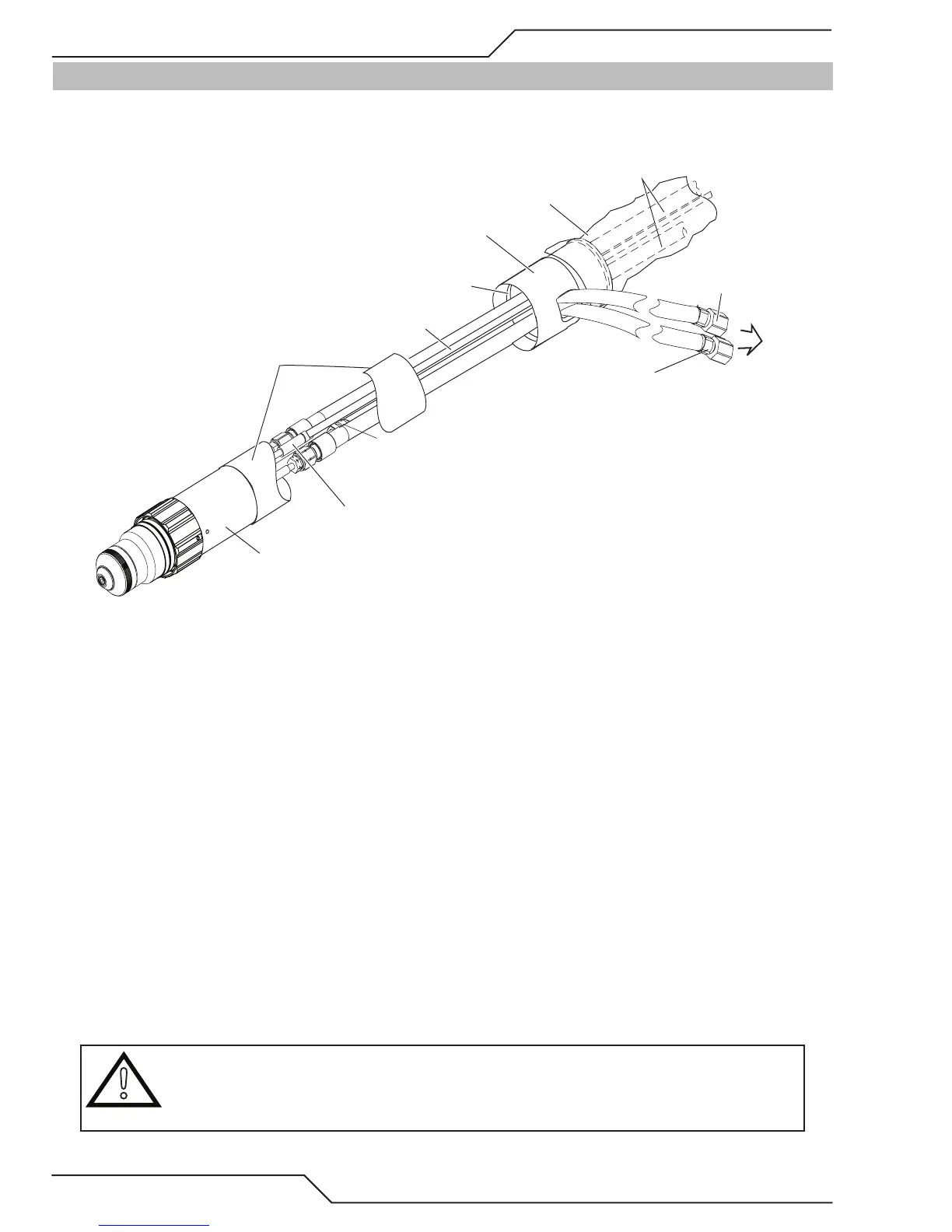
3.24 Connecting Torch
Connect the Torch as follows:
Art # A-09198_AB
Pilot Lead Connector
Torch Head Assembly
Mounting Tube
Torch Leads End Cap
Plasma Gas
(Left Hand Thread)
Shield Gas
(Right Hand Thread)
Coolant Supply
&
Power Lead (-)
Pilot Lead
Coolant Supply,
Coolant Return,
and Pilot Leads
Leads Cover
Groove for O-Ring
To Torch Valve
1. Lay out the torch leads on a clean, dry working surface.
2. Hold the Torch Leads End Cap stationary. Pull approximately 18” (0.5 m) of leads through the End Cap.
3. Remove and discard the protective end caps from the Mounting Tube.
4. Install the O-ring in the groove at the upper end of the Mounting Tube.
5. Install the Mounting Tube as follows:
a. Position the Mounting Tube at the end of the leads assemblies as shown.
b. Slide the Mounting Tube upward onto the leads assemblies.
c. Press the upper end of the Mounting Tube into the lower end of the Torch Leads End Cap. Ensure that the O-Ring on
the Tube engages the mating groove inside the Torch Leads End Cap.
d. Ensure that the Mounting Tube is free to rotate within the Torch Leads End Cap.
6. Connect the gas and coolant leads to the Torch Head.
a. Coolant supply and return connections to the Torch Head are of different lengths.
b. Plasma and secondary gas connections to the Torch Head are threaded differently; the plasma gas connection is
left-hand thread, the shield gas connection is right-hand thread.
c. Hold the Torch Head leads connectors stationary; turn the leads fittings with a wrench to secure the leads to the Torch
Head. Do not overtighten.
!
CAUTION
The gas and coolant leads include compression fittings. Do not use sealant on these connections.
Slowly apply pressure to the gas lines. Check for leaks at all connections before continuing. If
there are no leaks, shut off the gas supplies and continue with installation.