MAINTENANCE MANUAL
Effectivity: All
Page 11-13
Edition 2 | Rev. 1
SERIAL
NO.
PLACARD COLOUR LOCATION FIG.
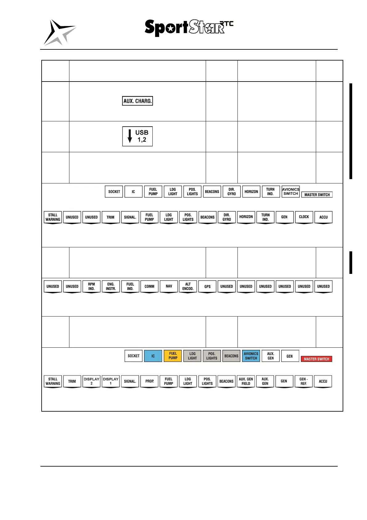
34.
Black /
white
L part of the instrument
panel at the auxiliary
generator signalling
light.
11-2
35.
Black /
white
R part of the instrument
panel at USB
connectors.
11-2
36.
Black /
white
L part of the instrument
panel at switches and
circuit breakers.
11-2
NOTE: The above specified layout of the placards applies to the standard design
of the airplane, it may vary depending on the installed equipment.
37.
Black /
white
R part of the instrument
panel at circuit
breakers.
11-2
NOTE: The above specified layout of the placards applies to the standard design
of the airplane, it may vary depending on the installed equipment.
38. Various
L part of the instrument
panel at circuit breakers
and circuit breakers.
11-2
NOTE: The above specified layout of the placards applies to the standard design
of the airplane, it may vary depending on the installed equipment.