XTP CrossPoint Series • Maintenance and Modifications 147
INPUTS
OUTPUTS
10
0-240V
50-60Hz
--
A MA
X
1−
4
5−
8
9−
1
2
13
−
16
1−
4
5−
8
9−12
13−16
L
AN
ACT
LINK
REMO
TE
R
S-232
/RS-422
RESET
OUT
XT
P
CP
4o
SA
AUD
IO
L
R
L R
L R
L
R
OUT
IN
X
TP
CP
4i
V
GA
AUD
I
O
L
R
L
R
L R
L R
IN
IN
IN
X
TP
C
P
4i
RS-
232 I
R
TxRx
TxRx
RS-
232
IR
T
x
R
x TxRx
RS-2
32 I
R
Tx
Rx Tx
Rx
RS-
23
2
IR
TxRx Tx Rx
S
IG
L
I
NK
XTP
PWR
AC
T
LIN
K
L
AN
S
IG
L
INK
XTP
PWR
AC
T
LI
N
K
L
A
N
SIG
L
INK
XTP
PWR
AC
T
LI
N
K
LAN
S
IG
L
INK
XTP
P
WR
ACT
LIN
K
L
AN
IR/
R
S
-
23
2 OV
E
R
X
TP
OUT
OUT
X
T
P
CP
4o
RS-
232 I
R
Tx
Rx Tx
Rx
RS-
232
IR
T
xR
x
Tx
Rx
RS-2
32
I
R
Tx
Rx
Tx
Rx
RS-
23
2
IR
TxRx Tx
Rx
SIG
L
I
NK
XTP
PWR
AC
T
LIN
K
L
AN
S
IG
L
INK
XTP
PWR
AC
T
LI
N
K
L
A
N
S
IG
L
INK
XTP
PWR
AC
T
LI
N
K
LAN
S
IG
L
INK
XTP
P
WR
AC
T
LIN
K
L
AN
IR/
R
S
-
23
2 OV
E
R
X
TP
IN
X
TP
CP
4
i
D
VI P
r
o
A
UDI
O
L
R
L
R
L
R
L R
IN
OUT
X
TP
C
P
4o D
V
I P
ro
A
UDI
O
L
R
L R
L R
L
R
OUT
OUT
X
T
P
CP
4o
H
DMI
AUD
IO
L
R
L
R
L
R
L
R
OUT
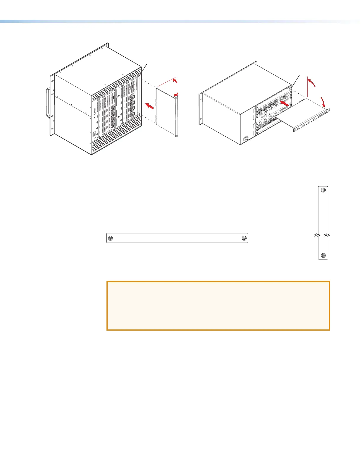
Align with
Plastic Guides
IN
X
T
P
CP
4i
HD
MI
A
UDI
O
L
R
L
R
L R
L R
IN
Knurled Knobs
90°
XTP CrossPoint 3200 XTP CrossPoint 1600
90°
Knurled Knobs
I
N
P
U
T
S
O
U
T
P
U
T
S
LAN
ACT
LINK
RESET
100-240V
50-60Hz
--A MAX
REMOTE
RS 232/RS42
2
D
ISCONNECT POWER
CORD BEFORE
SERVICING
IN
XTP CP 4i VGA
AUDIO
LRLRLR LR
IN
IN
XTP CP 4i VGA
AUDIO
LRLRLR LR
IN
IN
IN
XTP CP 4i
RS-232 IR
TxRx Tx Rx
RS-232 IR
TxRx Tx Rx
RS-232 IR
TxRx Tx Rx
RS-232 IR
TxRx Tx Rx
SIG LINK
XTP
PWR
ACT LINK
LAN
XTP
PWR
ACT LINK
LAN
XTP
PWR
ACT LINK
LAN
XTP
PWR
ACT LINK
LAN
IR/RS-232 OVER XTP
IN
IN
XTP CP 4i
RS-232 IR
TxRx Tx Rx
RS-232 IR
TxRx Tx Rx
RS-232 IR
TxRx Tx Rx
RS-232 IR
TxRx Tx Rx
SIG LINK
SIG LINK
SIG LINK
SIG LINK
SIG LINK
SIG LINK
SIG LINK
XTP
PWR
ACT LINK
LAN
XTP
PWR
ACT LINK
LAN
XTP
PWR
ACT LINK
LAN
XTP
PWR
ACT LINK
LAN
IR/RS-232 OVER XTP
OUT
OUT
XTP CP 4o
RS-232 IR
TxRx Tx Rx
RS-232 IR
TxRx Tx Rx
RS-232 IR
TxRx Tx Rx
RS-232 IR
TxRx Tx Rx
SIG LINK
XTP
PWR
ACT LINK
LAN
XTP
PWR
ACT LINK
LAN
XTP
PWR
ACT LINK
LAN
XTP
PWR
ACT LINK
LAN
IR/RS-232 OVER XTP
OUT
OUT
XTP CP 4o
RS-232 IR
TxRx Tx Rx
RS-232 IR
TxRx Tx Rx
RS-232 IR
TxRx Tx Rx
RS-232 IR
TxRx Tx Rx
SIG LINK
SIG LINK
SIG LINK
SIG LINK
SIG LINK
SIG LINK
SIG LINK
XTP
PWR
ACT LINK
LAN
XTP
PWR
ACT LINK
LAN
XTP
PWR
ACT LINK
LAN
XTP
PWR
ACT LINK
LAN
IR/RS-232 OVER XTP
OUT
XTP CP 4o SA
AUDIO
LRLRLR LR
OUT
IN
XTP CP 4i DVI Pro
AUDIO
LRLRLR LR
IN
IN
XTP CP 4i DVI Pro
AUDIO
LRLRLR LR
IN
OUT
XTP CP 4o DVI Pro
AUDIO
LRLRLR LR
OUT
OUT
XTP CP 4o DVI Pro
AUDIO
LRLRLR LR
OUT
IN
XTP CP 4i HDMI
AUDIO
LRLRLR LR
IN
IN
XTP CP 4i HDMI
AUDIO
LRLRLR LR
IN
OUT
XTP CP 4o HDMI
AUDIO
LRLRLR LR
OUT
OUT
XTP CP 4o HDMI
AUDIO
LRLRLR LR
OUT
Align with
Plastic Guides
Figure 74. Input or Output Board Replacement
Installing an Input or Output Board or Blank Panel
Install an input or output board or blank panel as follows:
1. For an input or output board, orient the board to be installed so that the silk-
screened word “In” or “Out” is right-side up and to the top (XTP CrossPoint 3200)
or to the left (XTP CrossPoint 1600) (see figure 75).
Figure 75. Board Orientation
2. For an input or output board, align the board with the top and bottom
(XTP CrossPoint 3200) or left and right (XTP CrossPoint 1600) chassis guides (see
figure 74).
ATTENTION:
• Ensure the board goes straight into the chassis, and not angled to either side.
Damage to the board may occur.
• Assurez-vous que la carte s’emboîte parfaitement dans le châssis, sans
aucune inclinaison latérale, étant donné les risques de détérioration de la
carte..
3. Gently slide the board or blank panel into the enclosure. For an input or output
board, slide the board toward the front panel until it meets resistance.
4. Gently seat the board or panel in the backplane.
5. Use a screwdriver to tighten the captive screws that lock the board or panel in place.
IN
IN