XTP CrossPoint Series • Operation 29
Operation
This section describes the front panel operation of the XTP CrossPoint Matrix Switcher,
including:
• Front Panel Controls and Indicators
• Front Panel Operations
• Rear Panel Operations
• Optimizing the Analog Audio
• RS-232 Insertion
• Troubleshooting
• Configuration Worksheets
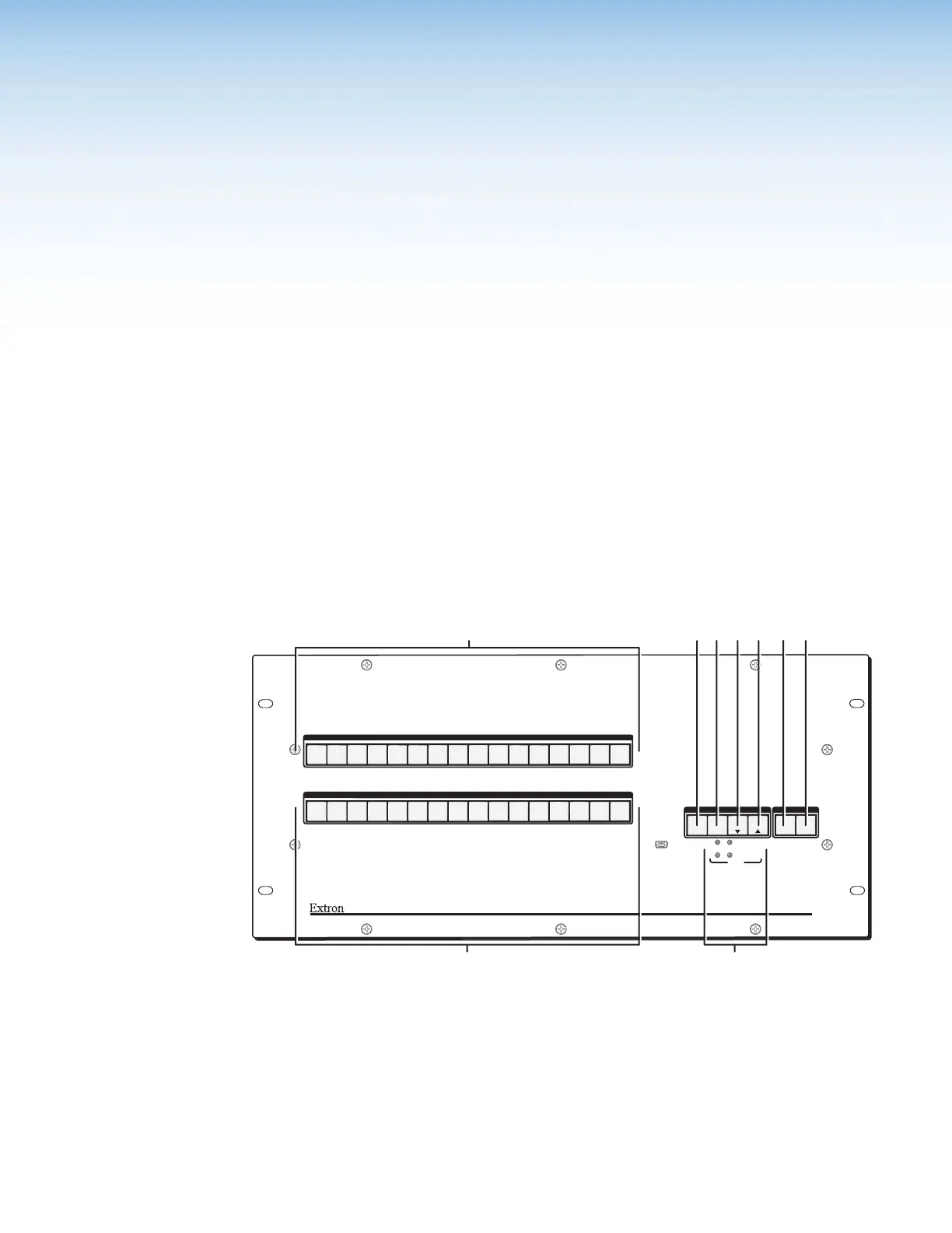
Front Panel Controls and Indicators
The front panel controls (see figure 28 and figure 29 on the next page) are grouped into two
sets. The input and output buttons,
A
and
B
, are grouped on the left side of the control
panel. The control buttons and video/audio (I/O) selection buttons,
C
through
H
, are
grouped on the right side of the panel.
AUDIO
PRIMARY
REDUNDANT
VIDEO
I/O
POWER
CONTROL
ENTERPRESET
VIEW
ESC
INPUTS
OUTPUTS
1
2
3
4
5
6 7
8
9
10
11
12
14
15
16
13
1
2
3
4
5
6 7
8
9
10
11
12
14
15
16
13
XTP CROSSPOINT 1600
XTP SERIES DIGITAL MATRIX SWITCHER
CONFIG
12
A
CDEF GH
Figure 28. Front Panel, XTP CrossPoint 1600 Matrix Switcher
A
Input buttons (see page 31)
B
Output buttons (see page 31)
C
Enter button (see page 32)
D
Preset button (see page 32)
E
View button (see page 33)
F
Esc button (see page 33)
G
Video button (see page 34)
H
Audio button (see page 34)
I
Power LEDs (see page 34)