XTP CrossPoint Series • Installation 27
Reset Button and LED
E
Reset button (see figure 2 on page 12 and figure 3 on page 13) — The
Reset button initiates four levels of matrix switcher reset. For resets, press and
hold the button while the matrix switcher is running or while you power up the
matrix switcher (see Rear Panel Operations on page 62 for details).
Power
F
AC power connector —
NOTE: See figure 2 on page 12 and figure 3 on page 13.
Plug a standard IEC power cord into this connector to connect the matrix switcher to a
100 VAC to 240 VAC, 50-60 Hz power source.
Front Panel Configuration Port and Power LEDs
CONTROL
ENTERPRESET
VIEW
ESC
XTP CrossPoint 3200
AUDIO
VIDEO
I/O
CONTROL
ENTERPRESET
VIEW
ESC
AUDIO
VIDEO
I/O
XTP CROSSPOINT 1600
XTP SERIES DIGITAL MATRIX SWITCHER
CONFIG
XTP CROSSPOINT 3200
XTP SERIES DIGITAL MATRIX SWITCHER
1
2
3
4
POWER
CONFIG
XTP CrossPoint 1600
PRIMARY
REDUNDANT
POWER
12
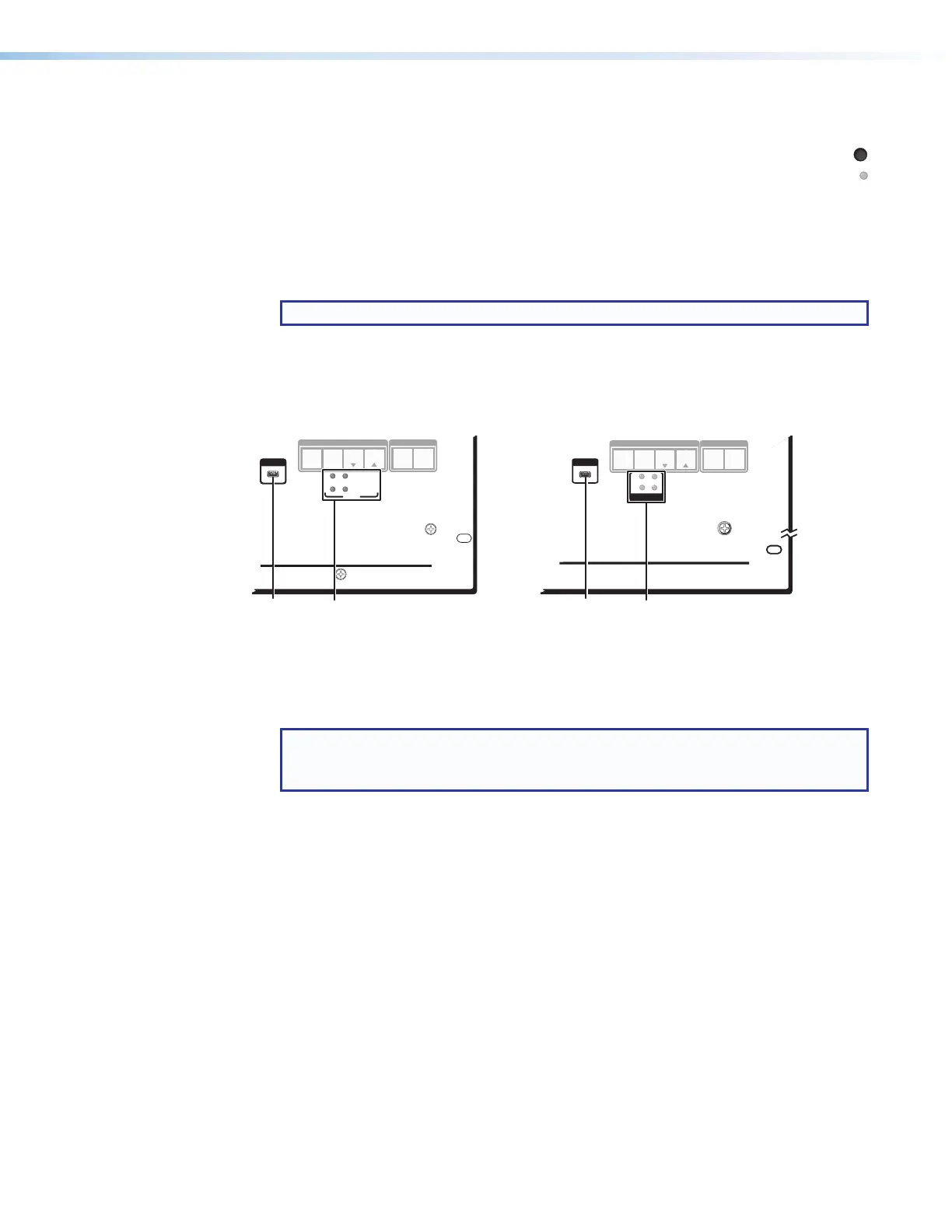
Figure 27. Front Panel Configuration (Config) Port and Power LEDs
A
Configuration port — This USB mini-B port serves a similar communications function
as the rear panel Remote port, but it is easier to access than the rear port after the
matrix switcher has been installed and cabled.
NOTE: A front panel Configuration port connection and a rear panel Remote port
connection can both be active at the same time. If commands are sent to both
simultaneously, the command that reaches the processor first is handled first.