XTP CrossPoint Series • Installation 23
ATTENTION:
• Do not overtighten the HDMI connector mounting screw. The shield it fastens
to is very thin and can easily be stripped.
• Ne serrez pas trop la vis de montage du connecteur HDMI. Le blindage auquel
elle est attachée est très fin et peut facilement être dénudé.
4. Loosely place the included tie wrap around the HDMI connector and the LockIt lacing
bracket as shown (
4
).
5. While holding the connector securely against the lacing bracket, use pliers or similar
tools to tighten the tie wrap, then remove any excess length (
5
).
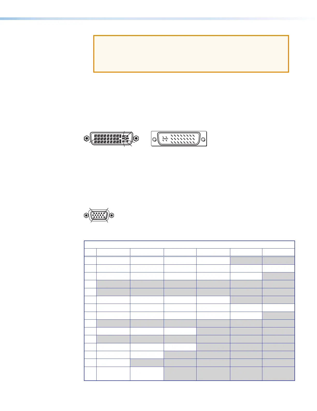
DVI connectors
Figure 21 defines the pin arrangement for the DVI connector.
Male Connector (cable)
Female Connector
1
9
8
17 24
C3 C4
C1 C2
C5
Figure 21. DVI Connectors
Analog video connectors
The 15-pin HD (VGA) universal analog input ports accept RGB (RGBHV, RGBs, RGsB), HDTV,
component video (bi- or tri-level sync), S-video, or composite video signals, and support
EDID emulation. Figure 22 shows the pinouts for each format type on the connector.
11
15
Figure 22. VGA Connectors
15-Pin HD Connector Pinout Table
Pin RGBHV RGBs RGsB Component S-video Composite
1 Red Red Red R-Y
2 Green Green Green/Sync Y Luma Video
3 Blue Blue Blue B-Y Chroma
4
5
6 Red return Red return Red return R-Y return
7 Green return Green return Green return Y return Luma return Video return
8 Blue return Blue return Blue return B-Y return C return
9
10 Ground Ground Ground
11
12 EDID/DDC EDID/DDC EDID/DDC
13 H sync C sync
14 V sync
15 EDID/DDC
return
EDID/DDC
return