XTP CrossPoint Series • Installation 26
Remote Control Ports
C
Remote RS-232/RS-422 port (see figure 2 on page 12 and figure 3 on
page 13) — Connect a host device, such as a computer or touchpanel control, to
the matrix switcher via this 9-pin D connector for serial RS-232 or RS-422 control (see
figure 26).
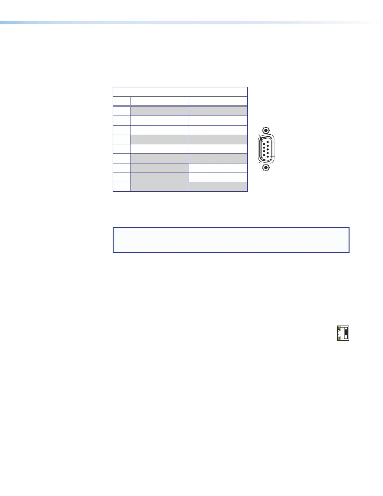
Remote RS-232 and RS-422 Pinout Table
Pin RS-232 RS-232
1
2 Tx Tx-
3 Rx Rx-
4
5 Gnd Gnd
6
7 Rx+
8 Tx+
9
Figure 26. Remote RS-232/RS-422 Port
See Programming Guide on page 76, for definitions of the SIS commands (serial
commands to control the matrix switcher and connected endpoints via this connector).
NOTE: The matrix switcher can support either the RS-232 or RS-422 serial
communication protocol, and can operate at 9600, 19200, 38400, or 115200
baud rates.
See Selecting the Rear Panel Remote Port Protocol and Baud Rate on
page 61 to configure the RS-232/RS-422 port from the front panel.
If desired, connect an MKP 2000 or MKP 3000 remote control panel to the rear panel
Remote port on the matrix switcher. See to the MKP 2000 Remote Control Panel User
Guide or the MKP 3000 User Guide for details.
Ethernet Connection
D
LAN port (see figure 2 and figure 3) — If desired, for IP control of the system,
connect the matrix switcher to a PC or to an Ethernet LAN via this RJ-45
connector. You can use a PC to control the networked matrix switcher with
SIS commands from anywhere in the world. You can also control the matrix switcher
from a PC that is running the Extron XTP Configuration Software or has downloaded
HTML pages from the matrix switcher (see TP connectors on page 19 to wire the
connector).
Act LED indicator — Indicates transmission of data packets on the RJ-45 connector.
This LED should blink quickly as the matrix switcher communicates.
Link LED indicator — Indicates that the matrix switcher is properly connected to an
Ethernet LAN. This LED should light steadily.
N
ACT
LINK