KT5500 5-
1
/
2
” Tong & CLInCHER® BaCKup
SECTIon ConTEnTS
3.14
TECHnICaL ManuaL
Mechanical Assembly Procedure (Continued):
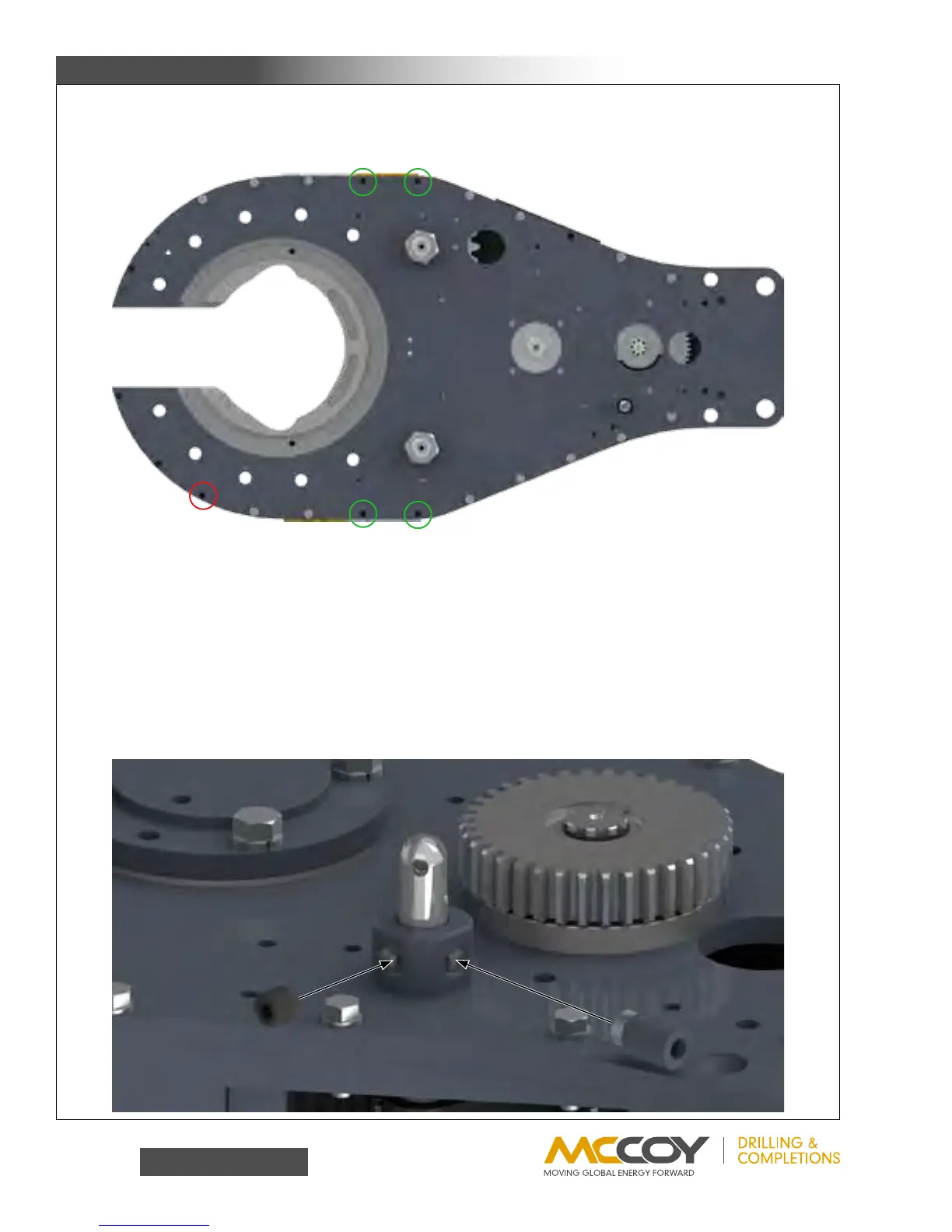
27. Securethetopplatewithfourteen3/8”UNCx1-1/2”hexboltsand3/8”lockwashers,andfive3/8”UNCx1”low-headheight
hexsocketheadcapscrews.Donotinstallfastenerscoincidentalwiththerigidslingbrackets(showncircledingreen)orthe
doorcylinderpost(showncircledinred).
28. Slidetheclutchbearingretainerspacer(PN1400-59A)overthebottomofthetopclutchbearingretainer(PN997-D11-59),and
mounttopclutchbearingretainerandspacertothetopplatewithtwo#10-24x3/4”hexsocketheadcapscrews.
29. Presstopclutchbearing(PN02-0002)intotopclutchbearingretainer.Insertclutchbearingbushing(PN997-60)shoulderside
upbetweenbearingandclutchshaft.
30. Secureclutchdrivegear(PN997-A3-61)tothetopoftheclutchshaftwithretainingsnapring(PN02-0001).
31. Installrotaryidlerpads(PN997-D20-125)overthetopoftherotaryidlershaftsandsecurewith1-1/2”UNFhexnylocknuts.
32. Pressremainingpinionbearingintothetoppinionbearingcap(PN997-D15-89)andsecureoverthetopofthepiniongearshaft
withfour1/2”UNCx1-1/4”hexboltsand1/2”lockwashers.
33. Slidethetopshifterbushing(PN101-0020)overtheshiftingshaftandthreadintothetopplateuntilsnug.
34. Threadthedetenttube(PN101-0019)intothetopshifterbushingasshown.Threadthree5/8”NCx5/8”hexsocketsetscrews
intotheremainingthreeportsinthetopshifterbushing-donotbottomoutthesetscrewsontheshiftingshaft,ortheshaftwill
notmove.