KT5500 5-
1
/
2
” Tong & CLInCHER® BaCKup
SECTIon ConTEnTS
3.15
TECHnICaL ManuaL
Mechanical Assembly Procedure (Continued):
35. Insertthedetentball(PN02-0018)throughtheendofthedetenttubeattachedtothetopshifterbushing,followedbythedetent
spring(PN997-0-64)Threada7/16”UNFjamnutontoa7/16”UNFx1-1/4”hexbolt,andthenthreadtheendoftheboltinto
thedetenttubeonthetopshifterbushing.
36. Inserttwo5/16”x3/4”productiongrounddowelpinsintothetopplate,oneoneithersideofthemotorshaftandgearcut-out,
directlybehindtheclutchassembly.
37. Positionthemotormount(PN1400-150)overthedowelpinsandsecuretothetopplateusingfour1/2”UNCx2”hexsocket
headcapscrews.
38. Inserta5/16”x5/16”x1-1/2”squarekeyintothekeyslotonthemotorshaft.Securethemotorgear(PN997-A10-149)tothe
hydraulicmotorshaftusingtwo3/8”UNCx3/8”flatpointhexsocketsetscrews.Ensurethatthemotorgearisorientedsothat
themachinedendofthemotorgear(theendinwhichthesetscrewsarethreaded)isflushwiththeendofthemotorshaft.
39. Mounthydraulicmotor(PN87-0110)tomotormount.SecuretheRHsideofthemotor(asseenfromthebackofthetong)with
two1/2”UNCx1-1/4”hexsocketheadcapscrewsand1/2”lockwashers.Thetorquegaugeholderweldment(PN1500-09-04A)
issecuredbythetwoLHmotorscrews-positionthetorquegaugeholderweldmentinplace,andsecureitandtheLHsideof
themotorwithtwo1/2”UNCx1-1/2”hexsocketheadcapscrewsand1/2”lockwashers.
40. Attachthetwo#20(1-1/4”)xJIC1”flangeelbows(PN02-9216)tothemotorportsusingtwo#20splitflangekits(PN02-9217).
41. Attachtheshifterlugweldment(PN101-0016)tothetopplateofthetongnexttothetopshifterbushingweldmentusingfour
3/8”UNCx1-1/4”hexboltsand3/8”lockwashers.
42. Connecttheshifterhandleweldment’s(PN1037-D-20B)pivotpointtothepivotpointoftheshifterlugweldmentusinga5/16”
x1-1/2”clevispin.Connecttheendoftheshifterhandleweldmenttothetopoftheshiftershaftusinga5/16”x1”clevispin.
Securetheclevispinswith.093”X1.125”hitchpins.
43. Positionthetwotopbrakebandlugweldments(RHLugWeldment=PN101-0132,LHLugWeldment=PN101-0134)onthe
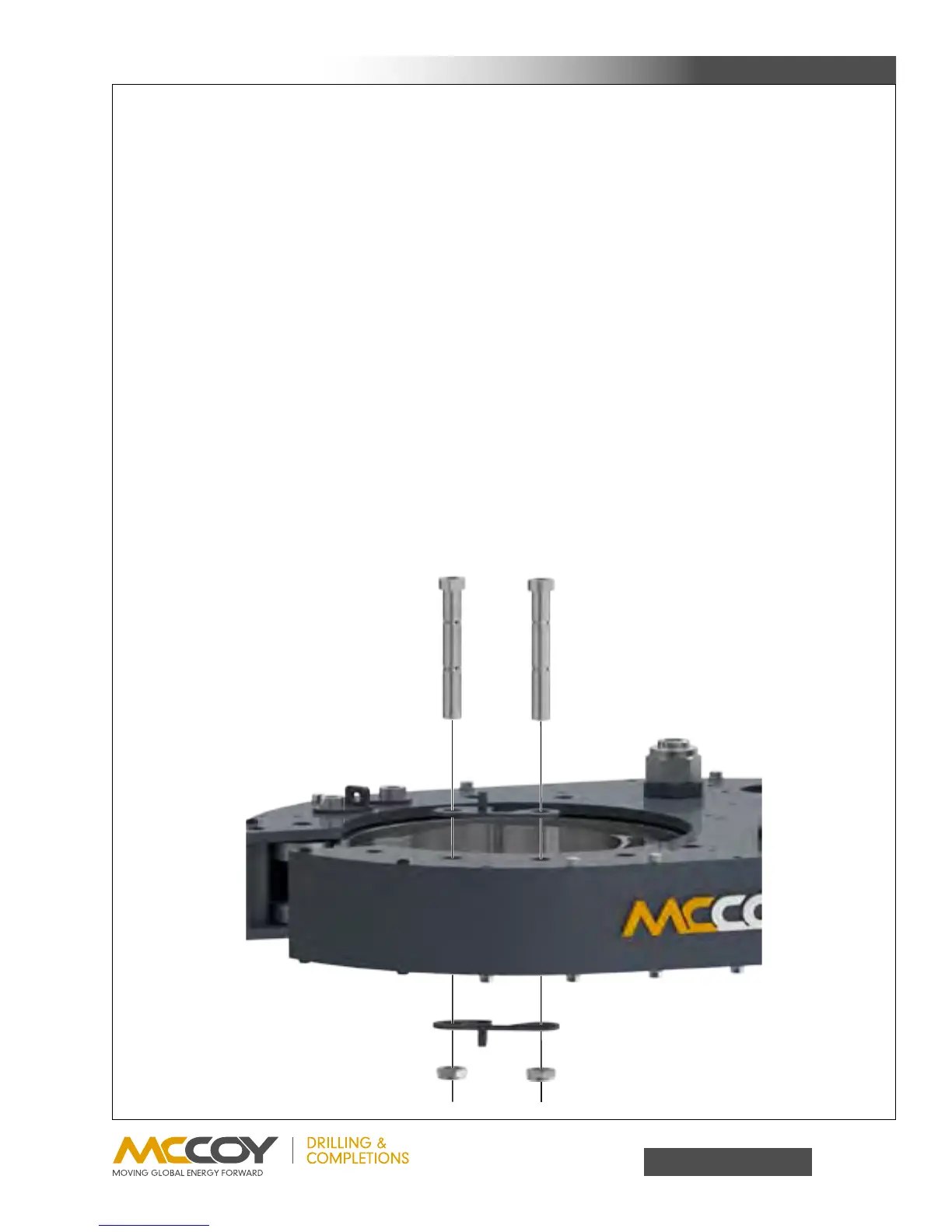
topplateovertheholesforthesupportrollershaftsasshowninthefollowingillustration.Insertfour“short”supportrollershafts
(PN101-3942)throughtheweldmentsandsupportrollercomponentsuntiltheshouldersoftheshaftsaretighttothelugweld-
ments.Slidethetwobottombrakebandlugweldments(LHLugWeldment=PN101-0132,RHLugWeldment=PN101-0134)
overthebottomofthesupportrollershaftsandsecurewith7/8”UNFthinnylocknuts.ASSEMBLY NOTE:Thesupportroller
assembliescoincidentalwiththebrakebandlugweldmentsDONOTuseflatwashers.