KT5500 5-
1
/
2
” Tong & CLInCHER® BaCKup
SECTIon ConTEnTS
3.16
TECHnICaL ManuaL
MaInTEnanCE
Mechanical Assembly Procedure (Continued):
44. Installtheremainingsupportrollershafts(excludingthedoorpivotrollershaft):
“Stand-Alone”Tongs(Models80-0420-5,80-0420-12)
i. Slidea7/8”narrowflatwasherovertheremainingfivesupportrollershafts(PN101-3942)andinsertintotheremaining
supportrollerassemblies(excludingthedoorpivotsupportroller).
ii. Secure the bottoms of the support roller shaftswith 7/8” narrow flat washers and 7/8” UNF thin nylock nuts with the
exceptionofthetwoshaftsdirectlybehindthebrakebandlugweldments.Thesetwoshaftswillserveaslegmountsin
afuturestep.
“Backup-Ready”Tongs(Models80-0420-3,80-0420-9,80-0420-14,80-0420-15)
i. Slidea7/8”narrowflatwasherovertheremaining“short”supportrollershaft(PN101-3942)andfour“long”supportroller
shafts(PN101-3944).InserttheshortshaftintothesupportrollerassemblydirectlyinfrontoftheRHbrakebandlugweld-
ment,andinsertthefour“long”shaftsintothefourremainingsupportrollerassemblies(twopersidedirectlybehindeach
brakebandlugweldment).
ii. SecurethebottomsoftheshortsupportrollershaftdirectlyinfrontoftheRHbrakebandlugweldmentwitha7/8”narrow
flatwasherand7/8”UNFthinnylocknut.Donotplacefastenersonthefourlongshaftsatthistime.
45. Installthirteencamfollowers(PN02-0016)intothebottomcageplate(PN1400-22)Secureeachwitha5/8”UNFnylockjam
nut.
46. Installthirteencamfollowers(PN02-0016)intothetopcageplate(PN1400-21)Secureeachwitha5/8”UNFnylockjamnut.
47. Supportthebottomcageplateinpositionbeneaththerotarygear,ensuringthecamfollowersarenestedwithinthegrooveinthe
rotarygear.Placethetopcageplateinpositionovertherotarygear,ensuringthecamfollowersarenestedwithinthegroove
intherotarygear
48. Placecageplatespacers(PN1064-38)betweenthetwocageplatesattheirconnectionpoints,oneintherearcentre,andone
eachsidejustinsidetherotarygear.
49. Slidea1/2”narrowflatwasherfollowedbythebackingpinspacer(PN101-4093)overa1/2”UNCx8”hexbolt.Slidethe
largerdiameterholeinthebackingpinretainer(PN101-4095)overthebackingpinspacer.
50. Attachthebottomcageplatetothetopcageplate.Usetwo1/2”NCx6”hexboltsatthefront,andthe1/2”x8”boltandspacer
assemblyintherearensuringthebackingpinspacerremainsbetweentheheadoftheboltandthetopofthetopcageplate.
51. Threadthe3/8UNCx1-1/2”threadedstud(PN101-4097)intothebackingpin(PN101-4042).
52. InsertthebackingpinandstudthroughthebottomofthebackingpinretainerinstalledinStep49.Slidetheshortbackingpin
spacer(PN101-4096)overthetopofthestud,andthreadthebackingpinknob(PN02-0017)ontothetopofthethreaded
stud.Liftthebackingpinandinsertintooneofthetworeceptaclesintherearofthetopcageplate.
53. Installthetopandbottomlinedbrakebandlugweldments(1064-D4-29).Securethebrakebandstothetopandbottomplates
usingonebrakebandretainer(PN101-0140)andtwo3/8”UNCx3/4”hexboltsand3/8”lockwashersattherearofeachbrake
band,anda3/8”UNFx2”hexboltand3/8”UNFhexnylocknutateachbrakebandlugweldment.
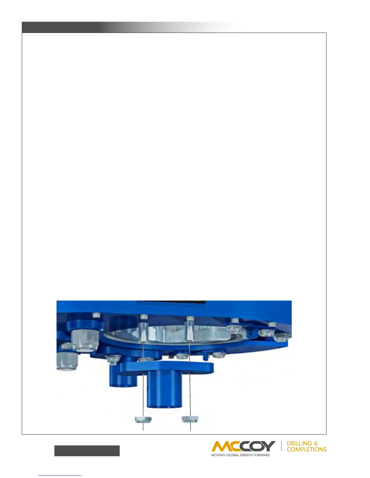
54. Installthetonglegs.Securethefrontleg mount mountweldmentstothebottomofthetongover the exposedsupportroller
shaftsusing7/8”UNFthinnylocknuts.SeethedrawingsandBOMonPp.5.32-5.33todeterminethecorrectlegmountweld-
mentsforyourapplication