KT5500 5-
1
/
2
” Tong & CLInCHER® BaCKup
SECTIon ConTEnTS
3.18
TECHnICaL ManuaL
MaInTEnanCE
Mechanical Assembly Procedure (Continued):
61. Attachtherigidslinghangerweldments(LHweldment=PN101-0150,RHweldment=PN101-0151)tothetopplateusing
two3/8”NCx1-3/4”bolts(outside),two3/8”NCx1”bolts(inside),andfour3/8”lockwashersperhanger.
62. Installinletcouplingsupportassembly(PN1050-C-175)tothetopplate,betweentheRHpinionidlerandRHrotaryidler,
usingtwo3/8”NCx1”hexboltsand3/8”lockwashers.Attachtheoutletcouplingsupportbase(PN101-0023)tothetop
platerightofthepinionbearingcapusingtwo3/8”NCx1”hexboltsand3/8”lockwashers,andattachtheadjustingplate
(PN101-0022)tothesupportbaseusingtwo3/8”NCx1”hexbolts,two3/8”flatwashers,andtwo3/8”UNCnylocknuts.
63. Installtwohydraulicvalvemountweldments(PN101-1442)tothetopplateoneithersideofthebrakebandretainerusing
one3/8”NCx1”hexboltand3/8”lockwasherperweldment.
64. Installthehydraulicvalveassemblytothevalvemountweldmentsusingone1/2”NCx4-1/2”hexboltand1/2”narrowflat
washerpervalvemount.Installmaininletandoutletlines,andtheremainderofthehydraulicconnections.Seethehydraulic
schematicforhydraulicconnections.
65. Slidethemasterliftinglink(PN02-0516)overtheadjustmenthelix(PN1053-1-H),andinstalltheadjustmenthelixintherigid
slingweldment(PN101-0112)usinga3/4”UNCx8”hexboltand3/4”UNCnylocknut.
66. Useacranetohoisttherigidslingweldment.Connecttherigidslingweldmenttotherigidslingmountinglugswithrigidsling
pins(PN1053-C-1C).Secureeachpinwithtwo0.148”x2.938”hitchpins.
67. Threada3/4”UNChexnutontoeachoftworigidslinglevelingadjustmentweldments(PN1053-C-1L).Threadtheleveling
adjustmentweldmentsintothefrontoftherigidslingweldmentmountingbrackets,roughlyadjustingthemsotherigidsling
isapproximatelyperpendiculartothetopplateofthetong(seeillustration3.H.10).
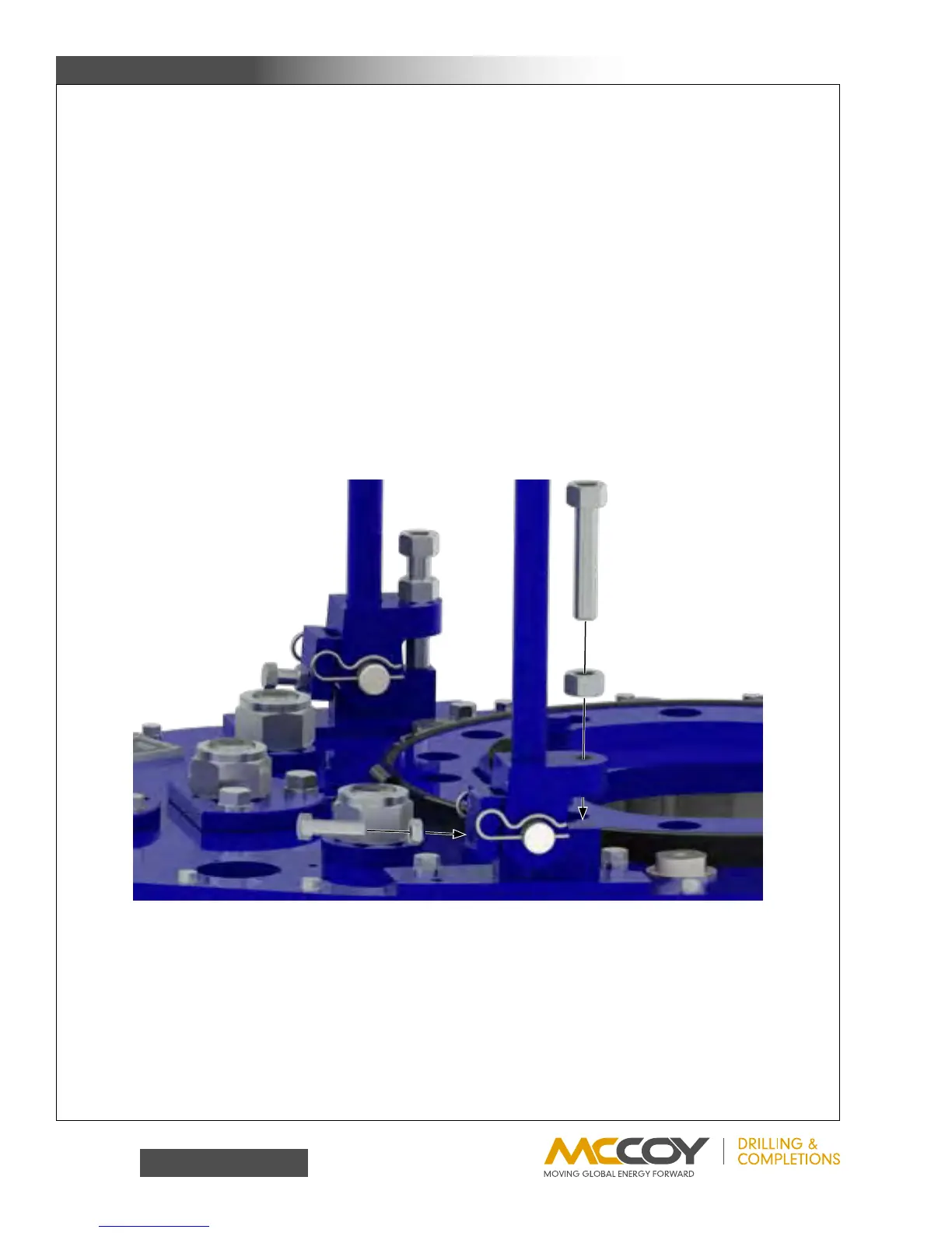
68. Thread1/2”UNChexnutsontotwo1/2”UNCx1-3/4”hexbolts.Threadtheboltsintotherearoftherigidslingweldment
mountingbrackets.(seefollowingillustration).
69. Useacraneandtemporaryslingtohoistthebackupassemblyontoasupportstructurenexttotheassemblylocationofthe
tong.Minimumheightforthebackupsupportsmustbe36”inordertoallowclearanceforinstallingthefrontlegs.
70. Attachtherearlegassemblytothetong:
a. Positionrearlegweldmentonaflatsurfacenearthetongassemblylocation.
● Model80-0420-16usesrearlegweldmentPN101-4487
● Model80-0422usesrearlegweldmentPN101-1547
● Model80-0421-3usesrearlegweldmentPN101-1987
b. Useacranetohoistthetongassemblyofftheassemblysurface.Bringthetongintocontactwiththerearleg,ensuring
thecranecontinuestosupporttheentireweightofthetong.Attachtherearlegweldmenttothetongusingtwo1-1/4”
UNCx8”hexboltsand1-1/4”UNChexnylocknuts,andtwo1”UNCx7”hexboltsand1”UNChexnylocknuts.