Chapter 9: Using a PLC With Your FT-50
9-7
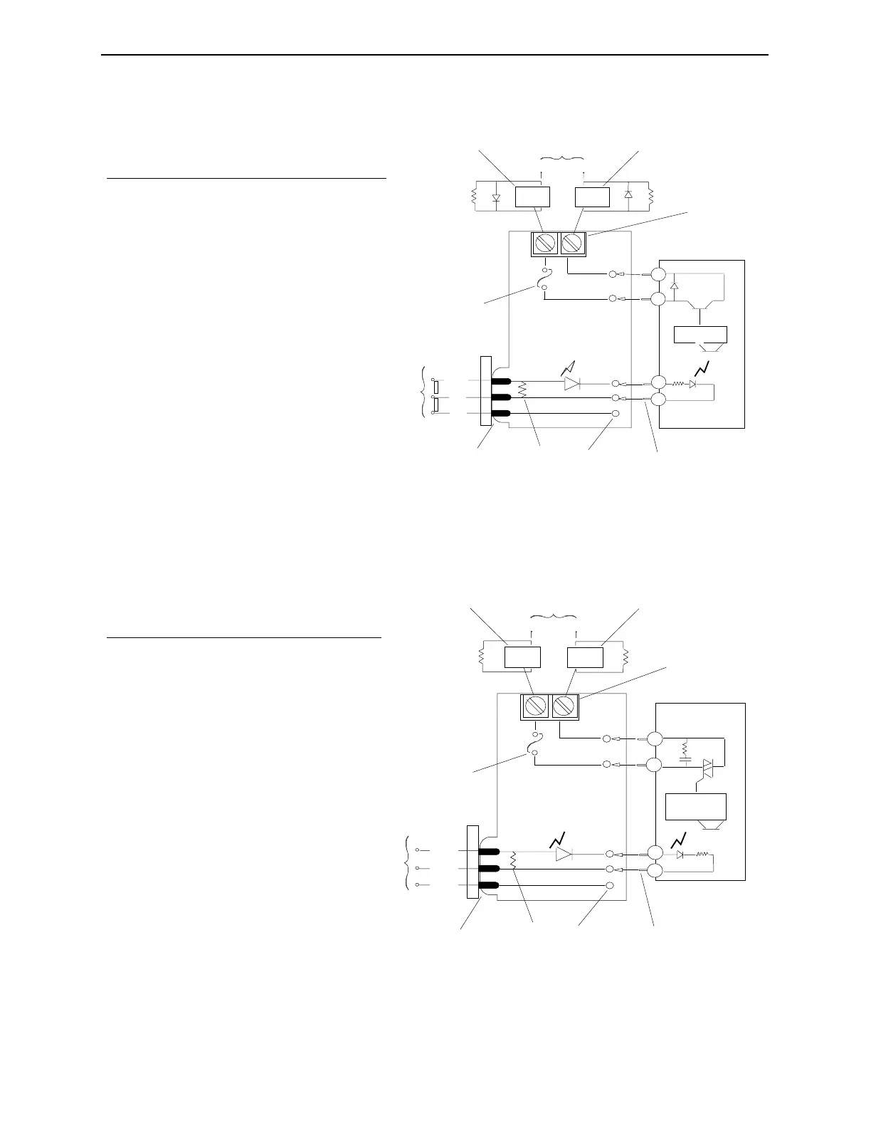
Figure 9-1. 0-60 Volts DC, 1 Amp max., 2 ma leakage, 10 ma min.
load.
Figure 9-2. 0-120 Volts AC, 1 Amp max., 2 ma leakage, 50 ma min.
load.
1
4
6
1
VDC
+
_
5A
L.E.D.
3.3K
7
8
11
+
-
-
3
2
Rc
13
12
5
9
2
3
4
10
14
15
16 16
Vcc
No. Description
1 Field
2 Diode must be used on inductive loads
3 Screw Terminals
4 Plug-in Module
5 Equivalent Circuit Only
6 Amplifier
7 Pins
8 Sockets in Mounting Rack
9 Pull-up Resistor
10 Edge Connector
11 Logic
12 Input
13 Ground (Common)
14 Mounting Rack
15 Fuse (Plug-in)
16 Load (Connected to either the positive or
negative side of the source)
7
1
VAC
5A
14
L.E.D.
3.3K
8
10
+
-
-
3
2
Rc
4
1
2
3
4
5
6
9
11
15
16 16
Vcc
12
13
No. Description
1 Field
2 Diode must be used on inductive loads
3 Screw Terminals
4 Plug-in Module
5 Equivalent Circuit Only
6 Zero Voltage Check
7 Pins
8 Sockets in Mounting Rack
9 Pull-up Resistor
10 Edge Connector
11 Logic
12 Input
13 Ground (Common)
14 Mounting Rack
15 Fuse (Plug-in)
16 Load (Connected to either the positive or
negative side of the source)
Industrial Dynamics Company, Ltd. Document 40255-0600