15
Parameters List
2-3 Parameters List
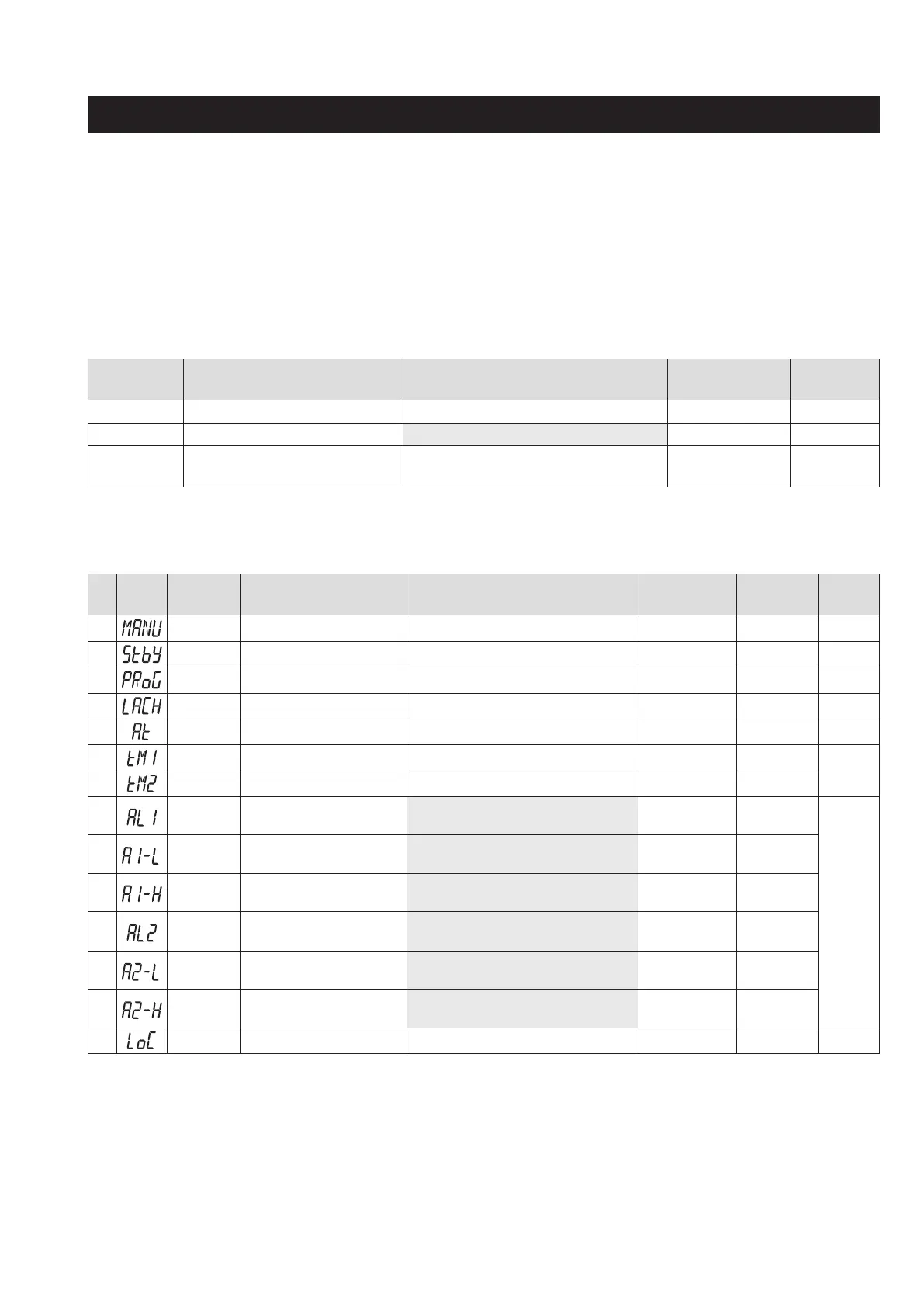
The following explains each channel parameter.
The range of the parameters in the shaded area indicates the industrial values.
When you change the PV input lower limit (P-SL), PV input upper limit (P-SU), or decimal place position (P-dP),
recongure all the industrial values.
Power-cycle the controller after you change the setpoint of the parameters of which No. column is shaded in gray.
Operation Mode
Parameter
symbol
Parameter name Setting range
Factory default
setting
Parameter
mask DSP
PV
Process Value ― ― ―
SV Set value Within the limit of 0 to 100% of FS
0
(°C)
―
MV Manipulated Variable (%) -5.0 to 105.0 (%)
-5.0
DSP14-
32768
1st block parameter
No Display
Parameter
symbol
Parameter name Setting range
Factory
default setting
Parameter
mask DSP
Reference
page
1
MANU
Manual mode selection oFF, oN oFF DSP13-32
20
2 Stby Standby setting oFF, oN oFF DSP1-1
21
4 PRoG Ramp soak control oFF, RUN, HLd oFF DSP1-2
22
5 LACH Alarm latch cancel oFF, RSt oFF DSP1-4
24
6 At Auto-tuning oFF, oN, L-oN oFF DSP1-8
25
7 tM-1 Timer 1 display ― ― DSP1-16
27
8 tM-2 Timer 2 display ― ― DSP1-32
10 AL1 Set value of alarm 1
Absolute value alarm: 0 to 100%FS
Deviation alarm: -100 to 100%FS
10 (°C)
DSP1-128
28
11 A1-L Lower limit value of alarm 1
Absolute value alarm: 0 to 100%FS,
Deviation alarm: -100 to 100%FS
10 (°C)
DSP2-1
12 A1-H Upper limit value of alarm 1
Absolute value alarm: 0 to 100%FS
Deviation alarm: -100 to 100%FS
10 (°C)
DSP2-2
13 AL2 Set value of alarm 2
Absolute value alarm: 0 to 100%FS
Deviation alarm: -100 to 100%FS
10 (°C)
DSP2-4
14 A2-L Lower limit value of alarm 2
Absolute value alarm: 0 to 100%FS
Deviation alarm: -100 to 100%FS
10 (°C)
DSP2-8
15 A2-H Upper limit value of alarm 2
Absolute value alarm: 0 to 100%FS
Deviation alarm: -100 to 100%FS
10 (°C)
DSP2-16
19 LoC Key lock 0 to 5 0 DSP3-1
29