61
3rd block parameter
A1oP
A2oP
Alarm 1, 2 options (101, 102)
[Description] –––––––––––––––––––––––––––––––––––––––––––––––––––––––
You can set the optional functions to the alarm 1 and the alarm 2, if you need. The three types of optional functions
are assigned for each bit.
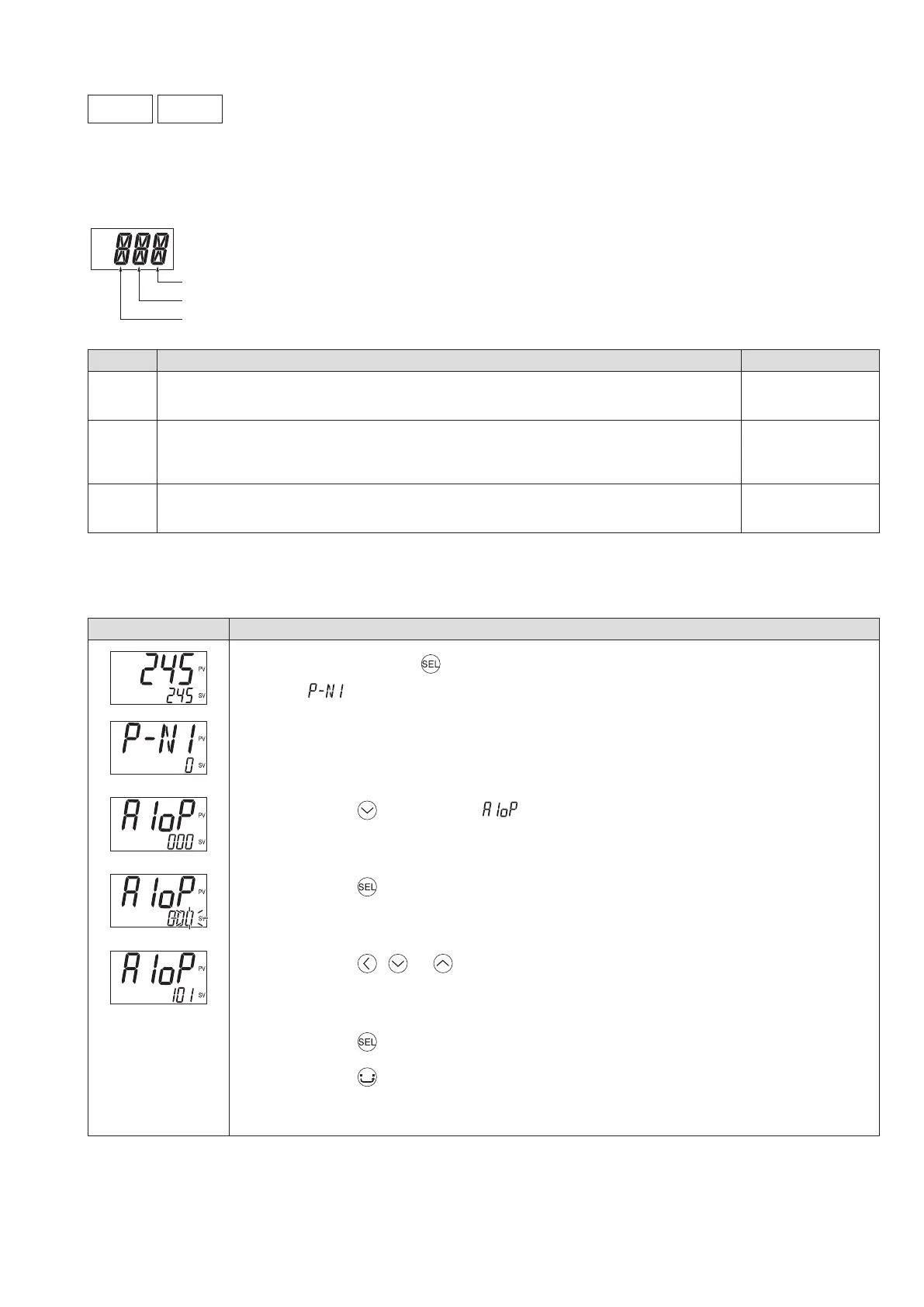
bit0
bit1
bit2
bit
Function
Setpoint
bit0
Alarm latch:
Latches (maintains) the state when an event occurs.
0 (OFF)
1 (ON)
bit1
Input error alarm:
Outputs when an input error (“UUUU” or “LLLL” is displayed) occurs.
Set the alarm type to “ 0 ” to use this function.
0 (OFF)
1 (ON)
bit2
Inverted output function:
Inverts the output and open the contact during an event occurs.
0 (OFF)
1 (ON)
[Setting example] ––––––––––––––––––––––––––––––––––––––––––––––––––
Adding the alarm latch and the converted output function to the alarm 1
Display Operating procedure
1.
Press and hold the key for about ve seconds during the SV/PV display.
appears.
2.
Press the key to display .
3.
Press the key.
The setpoint starts blinking.
4.
Press the , or keys to change “ 000 ” to “ 101 .”
5.
Press the key or wait for three seconds to save the change.
6.
Press the key.
The screen returns to the SV/PV display.