28
Parameter functions and setting procedure
AL1
A1-L
A1-H
Alarm 1 settings (010
,
011, 012)
AL2
A2-L
A2-H
Alarm 2 settings (013, 014, 015)
[Description] –––––––––––––––––––––––––––––––––––––––––––––––––––––––
Allows you to set the alarm setpoint.
AL1, AL2
: Alarm
A1-L, A2-L
: Low-limit alarm
A1-H, A2-H
: High-limit alarm
Setting range
Absolute value alarm: 0 to 100%FS
Deviation alarm: -100 to 100%FS
When the alarm type ([ALM1], [ALM2]) is set to 0 to 15, you can set the alarm 1, 2 ([AL1], [AL2]).
When the alarm type ([ALM1], [ALM2]) is set to any value other than 0 to 15, you can set the upper and lower
limits of alarm 1, 2 ([A1-H], [A2-H]
and
[A1-L], [A2-L]).
Related parameters:
• Alarm type 1, 2 [ ALM1], [ALM2] (see page 49)
• Alarm 1, 2 hysteresis [A1Hy], [A2Hy] (see page 59)
• Delay time 1, 2 [dLy1], [dLy2] (see page 59)
• Alarm 1, 2 options [A1oP], [A2oP] (see page 61)
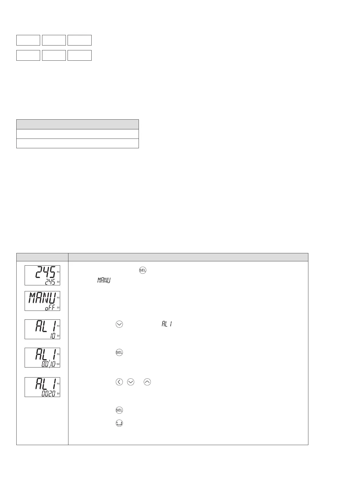
[Setting example] Setting the alarm 1 to “ 20 ” ––––––––––––––––––––––––––––
Display Operating procedure
1.
Press and hold the key for about one second during the SV/PV display.
appears.
2.
Press the key to display .
3.
Press the key.
The setpoint starts blinking.
4.
Press the , or keys to change “ 10 ” to “ 20 .”
5.
Press the key or wait for three seconds to save the change.
6.
Press the key.
The screen returns to the SV/PV display.